Energy Management System EMS
Controls Essential term
Reviewed October 2026 by Sergey Syrvachev
An Energy Management System (EMS) is the plant-level software that decides when a battery energy storage system charges, discharges or idles. On a grid-scale BESS it makes that call each moment and translates it into real and reactive power setpoints for the power conversion system (PCS).
It sits between external signals — market prices, ISO/utility dispatch, automatic generation control (AGC), or a power plant controller — and the plant's physical and contractual limits, running dispatch against those signals while staying inside state-of-charge, thermal, and grid-code envelopes.
Those limits are a set of independent ceilings, not a nested stack — POI export cap, PCS apparent-power rating, DC voltage window, cell temperature, or the throughput this year's warranty allowance still has left — and the lowest one in force at that moment sets what the plant can be asked to do in the next interval.
Which one that is changes through the day, with state of charge, ambient temperature and whether curtailment is in effect. It is distinct from the lower-level battery management system, which protects cells: the EMS owns dispatch strategy and revenue optimization, not cell-level safety.
Back to the free route: The grid — no cost, no account.
What it is (precise)
The EMS is the optimization and dispatch layer of a stationary storage plant. It ingests external requests (market schedules, frequency-response signals, AGC regulation commands, curtailment or POI export limits) and internal telemetry (aggregate state of charge, available power and energy reported up from the BMS, PCS availability, auxiliary load, thermal headroom), then computes real and reactive power commands.
Each setpoint flows down to one or more PCS units, which actuate it at the inverter. On multi-megawatt sites the EMS typically coordinates tens of containerized DC blocks and 1-5 MVA PCS skids so they behave as one aggregated resource at the point of interconnection (POI).
Architecturally the EMS sits near the top of a control hierarchy: cell/module BMS, rack or string controller, PCS controller, EMS, then SCADA and any market-facing bidding engine above it. It does not perform cell balancing or contactor protection — that is the battery management system's job — and it does not directly modulate the inverter's IGBTs — that is PCS firmware.
In hybrid or transmission-connected plants a power plant controller often runs the fast closed loop that regulates voltage, frequency response, and power factor at the POI, while the EMS handles the slower energy and state-of-charge optimization; in standalone BESS the two functions frequently ship as one software stack, so the scope split must be defined explicitly.
Defining that split means naming, function by function, which layer closes the loop and which one holds the limit. The workable division is an envelope down and a measurement back: the EMS publishes available charge and discharge power, the energy left to the top and bottom of the usable window, and any throughput or temperature restriction it wants respected; the PPC regulates P and Q at the POI inside that envelope and reports back the measured value plus a flag when the envelope could not be held.
The split is settled in parameter files, not in the architecture drawing — ramp gradients, response times and loss-of-comms fallback all live in PCS and PPC configuration, so an EMS built around a faster ramp than the inverters are set for will miss its own schedule every interval.
Why it matters in a real grid-scale project
On a grid-scale project the EMS is where most of the revenue and a large share of the warranty risk are realized. The same hardware can earn very different returns depending on how the EMS arbitrages energy, stacks ancillary services (frequency regulation, reserves, voltage support), and respects throughput limits.
Because LFP cell degradation is driven largely by cycle depth, throughput, and time spent at high state of charge, the dispatch policy directly determines whether the plant stays inside its contracted annual throughput — often expressed as a cycles-per-year or MWh-throughput cap in the warranty — and a poorly tuned strategy can breach capacity guarantees or pull augmentation forward by years.
Commercial dispatch is not one activity. In a day-ahead energy market the plant is scheduled hours ahead against forecast prices and then has to honour that schedule; in real time it follows five-minute prices or an AGC regulation signal; under a tolling agreement or capacity obligation it follows the offtaker's instruction and is judged on availability rather than price.
Most plants run several of these at once, and stacking them means holding power and energy aside for the obligation carrying the hardest penalty and selling what is left. Where a reserve product is involved the reservation is explicit — a resource carrying a reserve responsibility has to keep enough state of charge to sustain it for the service's defined duration — so an arbitrage trade that would empty the plant is not available to the optimizer, however wide the spread looks.
The economics have one property worth internalising: charging is a purchase, and round-trip efficiency taxes it. At 85-90 percent AC-to-AC, a megawatt-hour bought comes back as 0.85-0.90 MWh to sell, so the discharge price has to beat the charge price by roughly 11-18 percent before degradation, auxiliary consumption or anything else is covered.
Which rules the optimizer works inside is jurisdictional and has to be read from the specific market: FERC Order 841 required the US ISO/RTO markets under FERC jurisdiction to build participation models that respect a storage resource's physical characteristics, state of charge included; ERCOT sits outside that order with its own energy storage resource rules; CAISO's non-generator resource model lets a resource declare state-of-charge limits so awards stay feasible; national markets elsewhere differ again.
The EMS is also a compliance boundary. It must enforce POI export and import limits, honor grid-code requirements for ramp rate, frequency-watt and volt-var/volt-watt response, and curtail or trip on operator command. Getting this wrong has hard consequences: interconnection-agreement violations, failed witness tests, or unintended grid disturbances.
A well-designed EMS degrades gracefully — if communications to the market interface or a subset of PCS units drop, it falls back to a safe local mode (hold state of charge, zero setpoint, or last-good schedule) rather than dispatching blind. Loss-of-comms behavior is one of the first things a commissioning engineer should test.
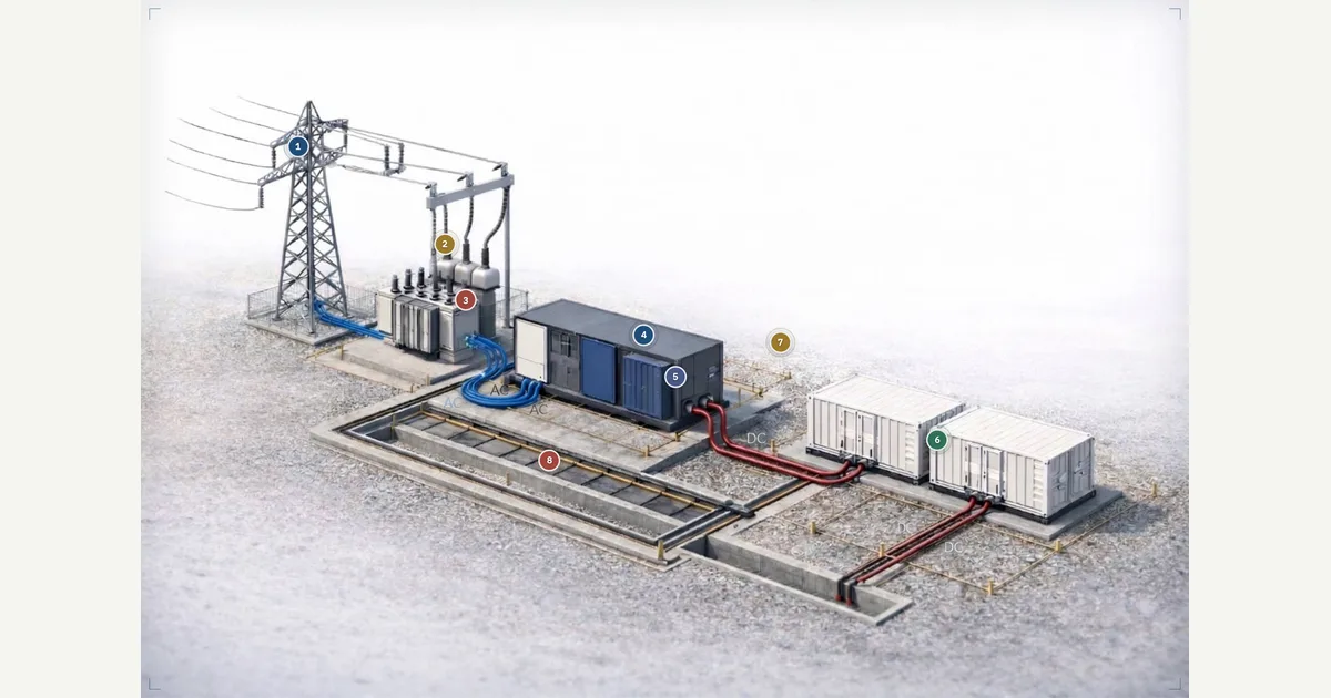 Interactive · bess.engineer ↗
 Key facts
| Control layer | Top of the plant dispatch chain: BMS -> PCS controller -> EMS -> PPC, with SCADA supervising beside that chain rather than inside it; owns dispatch and optimization, not cell protection |
|---|---|
| EMS/PPC handoff | Workable split: EMS publishes an available-power and remaining-energy envelope, the PPC regulates P and Q at the POI inside it — put the split in writing, since ramp, response and fallback behaviour sit in PCS/PPC parameter files |
| Setpoint cadence | Typically ~2-6 s refresh for AGC/frequency regulation (ERCOT/PJM signals ~2-4 s); response begins within ~0.2-2 s depending on service |
| Fast frequency response | Sub-second FFR executed by PCS/PPC droop logic; EMS supervises headroom and state of charge |
| Where actuation is configured (one vendor) | Power Electronics GEN3: active-power ramp default 50.0 %/s (range 0.1-3000.0 %/s), P(f) response to 90% of reference default 5.00 s, volt-watt P(V) default 10.0 s (0-90 s); comms-loss detected in 500 ms, then a configured fallback gradient (AEMO set, Australia: 1.43 %/s default, 0.35-655.00 %/s) |
| Comms protocols | Modbus TCP, DNP3, or IEC 61850 to the PCS; DNP3/ICCP telemetry to utility and SCADA above |
| Dispatch modes to serve | Day-ahead schedule, real-time price or AGC following, and tolled/capacity availability — most plants run several at once, reserving for the obligation with the hardest penalty first |
| Market participation model | Jurisdictional, so read your own market: FERC Order 841 set participation models for FERC-jurisdictional US ISO/RTO markets; ERCOT sits outside it with its own ESR rules; CAISO non-generator resources declare SOC limits to the market |
| Round-trip efficiency to manage | Typically 85-90% AC-to-AC at the POI for modern LFP systems |
| Arbitrage break-even | At 85-90% round-trip, the discharge price must beat the charge price by roughly 11-18% before degradation, auxiliaries or any other cost is covered |
| Auxiliary loads to net off | HVAC and controls commonly equivalent to ~1-3% of annual throughput |
| Dispatch band (displayed SOC) | A narrower band of displayed SOC (often roughly 5-95% or narrower), not the full 0-100% |
| Warranty throughput budget | Caps are often stated as cycles per year or MWh throughput; budget = EFC allowance x contract energy (365 EFC on 400 MWh = 146 GWh/yr), and it has to be paced through the year, not just logged |
| Availability guarantees | Integrated-system contracts typically target 95-98% (up to ~99%); check how EMS outages and comms failures are treated against the guarantee |
| Units coordinated | Tens of DC blocks and ~1-5 MVA PCS units aggregated to act as one resource at the POI |
| Interconnection standards | IEEE 1547 (distribution), IEEE 2800 (transmission-connected IBRs), plus the applicable national grid code |
| Cybersecurity | NERC CIP for market-registered North American plants; IEC 62443 widely referenced for control-system hardening |
| Safety standards (not the EMS's role) | UL 9540 (ESS product certification), UL 9540A (fire-propagation test method), NFPA 855, NFPA 68/69 — these govern the system and installation, not the dispatch software |
Typical values and standards
EMS control loops in BESS run fast by power-plant standards: AGC and frequency-regulation setpoints are typically refreshed every 2-6 seconds (ERCOT and PJM regulation signals arrive on roughly a 2-4 second cadence), and the plant is expected to begin responding within a few hundred milliseconds to a couple of seconds depending on the service.
Sub-second fast frequency response is usually executed by droop logic in the PCS or PPC layer, with the EMS supervising headroom. Communication to the PCS commonly uses Modbus TCP, DNP3, or IEC 61850 GOOSE/MMS; SCADA and market telemetry sit above, and utility telemetry commonly runs DNP3 or ICCP.
Some of the numbers that decide whether a setpoint is met sit in the converter rather than the EMS. Power Electronics' GEN3 software manual exposes active-power ramp gradients defaulting to 50.0 %/s across a 0.1-3000.0 %/s range, a P(f) frequency-response time to 90 percent of reference defaulting to 5.00 s within a 0-5 s range, and a volt-watt P(V) response time defaulting to 10.0 s within a 0-90 s range.
The same family's communication-failure protocol detects lost comms in 500 ms and then ramps on a configured fallback gradient — 1.43 %/s by default in the AEMO parameter set used for the Australian market, selectable from 0.35 to 655.00 %/s. Read those as one vendor's configuration rather than industry constants, but read them: this is where an EMS decision becomes plant behaviour.
The energy accounting the EMS manages has real numbers attached. Round-trip efficiency is typically 85-90 percent AC-to-AC at the POI for modern LFP plants, and auxiliary loads (HVAC, controls) commonly consume the equivalent of 1-3 percent of annual throughput, which the EMS must net off when reporting deliverable energy.
The EMS usually dispatches inside a narrower band of displayed SOC — often roughly 5-95 percent or narrower — rather than across the full 0-100 percent, and holds regulation headroom inside it. Contractual availability guarantees for the integrated system typically land in the 95-98 percent range (up to about 99 percent), with the EMS itself expected to be redundant or to fail to a safe state.
Standards divide by role. IEEE 1547 governs interconnection behavior for distribution-connected systems; IEEE 2800 covers transmission-connected inverter-based resources; the applicable national grid code sets ride-through and reactive-power duties the EMS and PPC must respect. Cybersecurity for market-registered plants in North America falls under NERC CIP, with IEC 62443 widely referenced for control-system hardening.
Safety certification is a separate lane: UL 9540 is the product safety certification for the energy storage system, UL 9540A is the fire-propagation test method that feeds NFPA 855 installation compliance, and NFPA 68/69 cover deflagration protection. None of those safety standards certify the EMS — it is a dispatch layer, not a protection device.
How it shows up in specs, studies and contracts
A working engineer meets the EMS first in the vendor scope matrix: which supplier provides EMS, PPC, and SCADA, and where each function lives. Check the points list (which signals the EMS reads and writes, at what rate), the protocol stack, and the stated response and ramp capabilities, because interconnection studies assume a specific plant-level control behavior.
The dynamic models submitted for the interconnection queue (PSCAD, PSS/E) embed plant-controller settings; if the delivered EMS/PPC tuning differs from the modeled behavior, the plant can fail commissioning witness tests or trigger a model revalidation with the ISO.
In contracts, the EMS surfaces in three places: the availability guarantee (how EMS outages count against the 95-98 percent target, and whether a comms failure is an excused event), the warranty cycling limits (the EMS must log throughput, cycle counts, and state-of-charge residency in a form the battery supplier accepts as evidence), and the capacity test procedure (the EMS executes the discharge profile that proves contracted energy at the POI, net of auxiliaries).
Useful questions to ask: who owns EMS software updates after COD, what happens to dispatch during an update, how is time synchronization handled for event forensics, and can the owner extract raw operational data without vendor mediation.
Those warranty limits are worth converting into operating terms before COD, because that is the form an EMS can act on. A cap stated in equivalent full cycles becomes an energy budget once multiplied by contract energy — one full cycle a day is 365 EFC, which on 400 MWh of contract energy is 146 GWh discharged in the year — and that budget has to be paced across the year rather than reconciled after it is spent.
Capacity warranties usually attach conditions beyond throughput: an average state-of-charge or residency limit, a cell-temperature band, sometimes a maximum C-rate, each of which the EMS has to respect and evidence. Check the baseline as well — a warranty baselined on nameplate rather than on measured COD capacity hands the supplier whatever the plant tested above label, which changes how much of the degradation curve the owner is actually protected on.
Common pitfalls
The most common trip-wire is the EMS/PPC scope gap: the EMS vendor assumes the PPC handles POI voltage regulation and the PPC vendor assumes the opposite, and the gap only appears during commissioning. A second is SOC accounting drift — the EMS plans dispatch on displayed SOC from the BMS, but displayed SOC reflects a usable window, not absolute cell SOC, and the two diverge as calibration ages; an EMS that ignores this over-promises energy near the window edges.
Third, metering reference: an EMS that optimizes against inverter-terminal power while the contract settles at the POI will systematically overstate deliverable energy by the transformer and auxiliary losses in between.
A fourth trap is double-committed capacity. Stacking only works if every product's reservation comes out of the same pool: headroom held against a reserve obligation is not also available to an arbitrage schedule, and energy sold day-ahead is not available to the real-time optimizer. The shortfall then surfaces in whichever product is measured most tightly, which is usually the one carrying the largest penalty.
A separate limit applies to power rather than energy — available discharge power falls near the bottom of the SOC window and at high cell temperature, and Power Electronics lists SOC-dependent power limiting as a GEN3 function — so an EMS offering flat rated MW across the whole window is offering something the converter will not actuate at the edges.
Finally, treat the EMS as critical infrastructure. It is a single logical point of failure for the whole plant's revenue, so specify redundancy or documented fail-safe behavior, tested failover, and a patching process that does not require taking the plant offline during market hours. Verify loss-of-comms and blackout-restart behavior during commissioning rather than trusting the manual — restart sequencing after a site outage (re-energize auxiliaries, close PCS, restore SCADA telemetry, resume dispatch) is exactly the kind of sequence that only surfaces its bugs when exercised end to end.
Common misconception
The EMS keeps the batteries safe and prevents thermal runaway.
In reality: Cell-level safety — overcurrent, over/under-voltage and temperature limits, contactor opening, and thermal-runaway protection — is the job of the battery management system, with product-level certification under UL 9540 and installation-level safety governed by NFPA 855 — fed by the UL 9540A fire-propagation test method — and NFPA 68/69. The EMS optimizes and dispatches power and respects the limits handed up from the BMS and PCS; it is a strategy and revenue layer, not a primary protection device.
Visuals & further reading
- Interactive: Plant Control Command Path Interactive visual · bess.engineer
- Interactive: Revenue Stacking Example Interactive visual · bess.engineer
- Interactive: ERCOT FFR Dispatch Timeline Interactive visual · bess.engineer
- How a Grid-Scale BESS Works: From Cell to Grid Article
- How Grid Batteries Make Money: BESS Revenue Streams in 2026 Article
- How Frequency Regulation Pays Batteries — and Why That Paycheck Shrinks Article
- Power Plant Controller Glossary
- Control hierarchy Glossary
- Automatic generation control Glossary
- Dispatch Glossary
- SOC window Glossary
- Energy throughput Glossary
- Equivalent full cycle Glossary
- Capacity warranty Glossary
- Point of Interconnection Glossary
Energy Management System, in context.
The Grid-Scale BESS course covers energy management system — and the rest of the system — from the ground up, the way it actually gets deployed.