Battery Management System BMS
Controls Essential term
Reviewed October 2026 by Sergey Syrvachev
A Battery Management System (BMS) is the lowest control layer inside a grid-scale battery, embedded in the racks and modules that fill each enclosure. It continuously measures per-cell voltage (millivolt resolution), module temperature, and string current, manages cell balancing, estimates state of charge (SOC) and state of health (SOH), and enforces hard protective limits computed from the limiting cell, not the fleet average.
When conditions exceed safe bounds it opens the rack-level DC contactors — typically rated for the full 1500 VDC bus — and disconnects the string. It is the battery's first and fastest layer of electrical and thermal protection, and the layer every higher controller must obey.
Back to the free route: The grid — no cost, no account.
What it is (precise)
In a utility-scale system the BMS is a three-layer hierarchy. A module-level board (BMU, sometimes called a slave or cell-monitoring unit) samples the individual LFP cells in one module — commonly a few dozen cells per module board. A full 1500 V rack string stacks several hundred of those cells in series across its modules. A rack- or string-level controller (BCU) aggregates the module boards, computes SOC and SOH, runs balancing, and drives the rack contactors and pre-charge circuit (which safely equalizes voltage across the DC bus before the main contactors close).
A system- or bank-level master (BAU) coordinates the racks within an enclosure, arbitrates which strings may close onto the shared DC bus, and reports one consolidated envelope upward. Vendor naming varies — module boards also appear as CMUs, and some stacks call the top layer a battery control system (BCS) or system BMS — but the three-layer split of sense, aggregate, coordinate is near-universal.
The BMS sits below the energy management system and the PCS controls in the plant hierarchy — it never decides how much power to dispatch, but it publishes the charge and discharge current limits inside which every higher layer is allowed to operate. Read bottom-up, the control chain is cell sensing → module BMU → rack BCU → bank BAU → EMS and plant controller: protection authority concentrated at the bottom, dispatch authority at the top, and the BMS-published limits are the contract between them.
When a power plant controller pushes a setpoint down through the EMS to the inverters, the request is ultimately clipped against the BMS-reported limits of the healthy strings. Its core jobs are measurement, estimation, balancing, and protection: tripping on over/under-voltage, over-temperature, over-current, and isolation faults, and signalling those faults to the PCS and site controller.
The limits themselves are weakest-cell logic in action. Every cell in a series string carries the same current, so the first cell to reach a bound ends charge or discharge for the whole string — which is why the BMS keys its charge limit on the highest cell voltage and the temperature extremes (cold restricts charge acceptance hardest), and its discharge limit on the lowest cell and the hottest module.
As any cell nears a bound the published limit tapers toward zero rather than stepping, so upstream controllers see a shrinking envelope and back off smoothly; an instant contactor trip is reserved for genuine faults. The series arithmetic behind this — why one cell caps a string of several hundred — is covered under weakest-cell limitation and cell imbalance.
Why it matters in a real grid-scale project
Commercially, the BMS sets the deliverable capacity and the warranty. SOC and SOH estimates feed availability and capacity guarantees, and the BMS-defined SOC window and operating conditions set the terms under which metered round-trip-efficiency guarantees are verified at the AC meter. The manufacturer's allowable operating envelope — temperature, C-rate, depth-of-discharge, voltage window — is what the warranty is written against.
Drift or mis-calibration in SOC directly erodes usable energy at the point of interconnection and can trigger liquidated damages on a capacity test. BMS-imposed current derates (a hot module, a lagging cell) are also the most common reason a plant delivers less than nameplate power on a summer afternoon, which shows up as missed dispatch instructions and availability penalties.
From a safety and code standpoint the BMS is the first link in the layered protection chain that NFPA 855 and UL 9540 assume exists. It is expected to detect an incipient cell fault — abnormal voltage, temperature, or a rising-rate signature — and isolate the string before the condition propagates toward thermal runaway. Because a single BMS can fail, the codes deliberately backstop it with independent detection and mitigation layers (detailed in the misconception below): the BMS is necessary but never sufficient on its own.
Balancing deserves its own commercial note. Stationary designs almost universally use passive resistive bleed: the strongest cells are trickle-discharged so the weakest cell does not prematurely hit a voltage limit and clip the usable capacity of the entire series string.
Active balancing — shuttling charge between cells instead of burning it — exists but remains rare in stationary racks; the trade is covered under cell balancing. A few percent of imbalance strands energy in every rack, and across the hundreds of racks in a full plant that translates directly into stranded megawatt-hours — so balancing effectiveness is quietly one of the levers behind measured versus contracted energy.
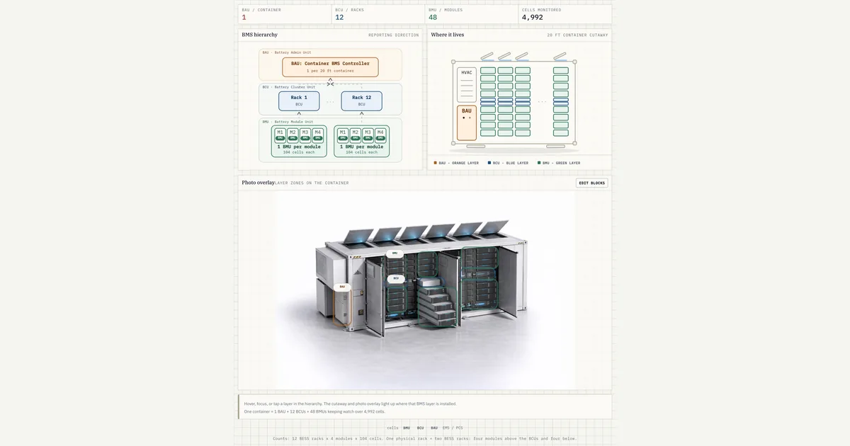 Interactive · bess.engineer ↗
 Key facts
| LFP cell voltage window | ~2.5–3.65 V (nominal ~3.2 V) |
|---|---|
| NMC window (contrast) | ~3.0–4.2 V, more thermally sensitive |
| Typical operating temperature | ~15–35 C band; hard cutoffs and derates beyond |
| Cell-voltage measurement accuracy | typically ±5 mV per cell |
| SOC estimate accuracy | ~2–5% between recalibration events |
| Balancing (stationary LFP) | passive resistive bleed, tens to low hundreds of mA per cell |
| Architecture | 3 layers: module BMU → rack BCU → bank/system BAU (vendor names vary) |
| Control position | Below EMS/PCS; publishes charge/discharge limits all layers must obey |
| Limit computation | Charge limit keys on the highest/hottest cell, discharge on the lowest; limits taper near bounds — computed from the limiting cell, never the average |
| DC bus / contactors | rack contactors rated for the full DC bus, typically ≤1500 VDC |
| Sampling / reporting | cell scan ~100 ms–1 s; upstream data ~1–5 s |
| Certification map | UL 1973 (cell to pack/rack), IEC 62619 (cells and batteries), UL 9540 (system cert), UL 9540A (fire test method), NFPA 855 (installation) |
| Comms | CAN inside racks; Modbus TCP or IEC 61850 to PCS/EMS/SCADA |
Typical values and standards
For LFP, cells are protected roughly between 2.5 V and 3.65 V with a nominal near 3.2 V; NMC — the higher-energy-density contrast, now rare in new stationary projects — runs a wider window around 3.0 to 4.2 V and is more thermally sensitive. Practical operating temperature is typically held in a 15 to 35 C band, with hard cutoffs and derates beyond it.
Cell-voltage measurement accuracy is typically on the order of plus or minus 5 mV, temperature accuracy around plus or minus 1 to 2 C, and SOC estimation accuracy in the range of 2 to 5 percent between calibration events. Passive balancing currents are modest — tens to low hundreds of milliamps per cell.
The certification map matters and is frequently mangled. UL 1973 covers the battery itself from cell to pack and rack, including an evaluation of the BMS protections; IEC 62619 is the corresponding safety standard for lithium cells and batteries in industrial applications.
UL 9540 certifies the complete energy storage system as a product — batteries, BMS, PCS, and controls together — while UL 9540A is not a certification at all but the test method that characterizes fire and thermal-runaway propagation, producing data used for NFPA 855 compliance. NFPA 855 governs the installation. A specification that asks for "UL 9540A certified" equipment is asking for something that does not exist; ask for the 9540A test report instead.
Communications are typically CAN bus inside the rack hierarchy and Modbus TCP (or increasingly IEC 61850 at large sites) from the bank-level controller up to the PCS, EMS, and SCADA. Sampling is fast at the bottom — cell voltages scanned every 100 ms to 1 s — while consolidated data moves upward at 1 to 5 second intervals. That asymmetry is deliberate: protection decisions happen locally at rack speed, and only summarized envelopes and alarms need to travel up the plant network.
How it shows up in specs, studies and contracts
In a battery datasheet, the BMS appears as the voltage window, the temperature envelope, the maximum charge and discharge C-rate, and the SOC operating range — and those numbers define usable energy, not the cell arithmetic. In the supply contract and warranty, look for the cycling and temperature conditions the guarantee assumes, who owns the BMS data, and what logging the operator must maintain to keep the warranty valid; most degradation warranties are void if operation strays outside the BMS-enforced envelope, which makes the envelope itself a contract document.
During commissioning and capacity testing, the BMS is the measurement instrument: the test procedure will cite BMS-reported SOC, and disputes usually reduce to whether displayed SOC matches coulomb-counted (current-integrated) energy at the meter.
In operations, the SCADA point list should expose per-rack SOC, SOH, limits, and fault words (bit-coded status registers that flag each active alarm) — insist on rack-level granularity, because a fleet average hides the one derated string that caps plant power. Questions worth asking every vendor: what SOC algorithm and recalibration behavior is used, how limits are computed and ramped, whether firmware updates are remote, and what happens to data access if the integrator disappears.
Common pitfalls
The classic traps are definitional. Displayed SOC is not absolute SOC: vendors map the usable window to 0 to 100 percent, so "0 percent" still leaves buffer energy in the cells, and two vendors' SOC numbers are not comparable without the mapping. SOC is not SOH — one is the fuel gauge, the other is the shrinking size of the tank — and augmentation planning runs on SOH trajectories, not SOC logs.
Unlike an EV pack, a stationary BMS optimizes for calendar life and warranty compliance over the last few percent of range, so its limits are deliberately conservative; treating BMS-limited power as a defect rather than designed behavior is a recurring source of owner-vendor friction. The same misreading appears in energy models that take the datasheet C-rate as a constant: the published limit is dynamic — SOC, temperature and cell spread all move it — and the derating entry covers how those envelopes are specified.
Sources & standards
Common misconception
The BMS by itself prevents thermal runaway and fires.
In reality: The BMS is the first protective layer — it detects and isolates faulty strings — but it can fail and is deliberately backstopped. NFPA 855 and UL 9540 assume independent gas/smoke detection, deflagration venting (NFPA 68) or explosion prevention (NFPA 69), and fire-propagation data from the UL 9540A test method. The BMS is necessary but not sufficient.
Visuals & further reading
- Interactive: BMS Three-Layer Structure Interactive visual · bess.engineer
- Interactive: Plant Control Command Path Interactive visual · bess.engineer
- Interactive: BESS Container Controls Interactive visual · bess.engineer
- Interactive: Inside a Lithium-Ion Cell Interactive visual · bess.engineer
- BESS Commissioning and Capacity Testing Article
- Weakest-cell limitation Glossary
- Cell Balancing Glossary
- Energy Management System Glossary
Battery Management System, in context.
The Grid-Scale BESS course covers battery management system — and the rest of the system — from the ground up, the way it actually gets deployed.