Point of Interconnection POI
PCS & grid Essential term
Reviewed October 2026 by Sergey Syrvachev
The Point of Interconnection (POI) is the precise electrical boundary where a grid-scale BESS plant connects to the utility system — the grid connection point, called the point of connection (POC) in UK and Australian practice — usually the high-voltage side of the main step-up transformer, or the substation revenue meter, anywhere from roughly 12.47 kV on a distribution feeder to 345 kV or higher on a transmission tie.
It is the contractually defined node where the plant's deliverable power, energy, voltage, and reactive support are measured and enforced. Every grid-code and commercial obligation is judged here, not at the inverter terminals — so you meet the POI on the interconnection one-line, in the offtake contract, and on every efficiency guarantee you review.
Back to the free route: Electrical foundations — no cost, no account.
The point of interconnection, and how it relates to the PCC
The POI — closely related to the point of common coupling (PCC), and often labelled the point of measurement in interconnection practice — is the single node named in the interconnection agreement where ownership passes from the project to the grid operator.
In a typical utility-scale BESS, power flows from LFP cells through the DC bus, the power conversion system, a low-voltage step-up transformer, the medium-voltage collection system, and finally the main power transformer (MPT). The POI is defined at the HV bushings of that MPT, or at the revenue meter on the utility side of the main breaker.
Because it sits at the very end of the power chain, the POI is downstream of every conversion stage and every parasitic load. A number quoted at the POI is fundamentally different from the same number at the inverter or the rack: the gap between them is the cumulative loss budget of the whole plant. It is also where the site's MV / LV / HV voltage tiers finally collapse into one metered node, so treat POI-net and inverter-gross as two quantities you never swap in a calculation.
The vocabulary is not fully standardized, and the differences carry money. IEEE 1547 distinguishes the point of common coupling from the point of connection of an individual unit, and defines a reference point of applicability where requirements are evaluated. Transmission agreements name a POI and, separately, a point of change of ownership that can sit elsewhere.
Regional vocabulary shifts too: UK practice says point of connection (POC) or grid connection point, and Australia's NEM simply says connection point — all naming the same contractual boundary. Never assume the terms coincide — read the agreement's one-line exhibit and confirm which bus and bushing it labels.
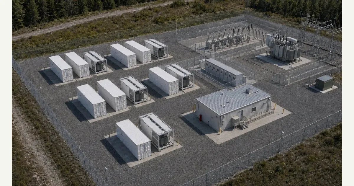 Interactive · bess.engineer ↗
 Numbers
Key facts
| Typical physical location | HV bushings of the main power transformer, or the utility revenue meter |
|---|---|
| Reference-plane rule | Compliance and settlement judged at the POI, not at the inverter/PCS terminals |
| Also known as | Point of Common Coupling (PCC), point of measurement, point of connection / POC (UK), grid connection point, connection point (AU NEM) — definitions differ; read the one-line exhibit |
| Distribution POI voltages (US) | Commonly 12.47 / 13.8 / 24.9 / 34.5 kV |
| Transmission POI voltages (US) | 69 / 115 / 138 / 230 / 345 kV, occasionally 500 kV |
| Governing standard — distribution | IEEE 1547-2018 (DER interconnection) |
| Governing standard — transmission IBR | IEEE 2800-2022, plus NERC reliability standards |
| Power factor at POI (FERC Order 827) | Capability of ~0.95 leading to 0.95 lagging required of new non-synchronous resources |
| Harmonic limits | IEEE 519, assessed at the PCC |
| Gross-to-net loss budget | RTE ~85–90% AC-AC at POI; MPT ~0.5–1%, collection ~0.5–1.5%, aux ~1–3% |
| LGIA threshold (FERC pro forma) | Historically >20 MW (SGIA at or below) |
| Storage-specific quirk | Bidirectional metering — every cycle's energy crosses the node twice (charge in, discharge out), so station losses are paid in both directions |
Typical values and standards
The gap between gross (inverter/DC) and net (POI) is the loss budget. Round-trip efficiency for a modern LFP plant is often on the order of 85–90% AC-to-AC measured at the POI, with the MPT typically absorbing about 0.5–1%, the MV collection system another 0.5–1.5%, and station auxiliaries roughly 1–3% depending on duty cycle. In practice that means a few percent of extra inverter capacity and often 10% or more of extra usable energy just to net the contracted figure at the boundary.
POI voltage is fixed by the interconnection study and spans a wide range: US distribution ties commonly land at 12.47, 13.8, 24.9, or 34.5 kV, while transmission projects connect at 69, 115, 138, 230, 345, or occasionally 500 kV. Compliance is governed by IEEE 1547-2018 for distribution-connected resources and IEEE 2800-2022 for transmission-connected inverter-based resources, alongside NERC reliability standards for ride-through, model quality, and protection. Harmonics injected by the plant are assessed against IEEE 519 limits at the PCC.
Regulatory numbers attach to the POI as well. In FERC jurisdictions the pro forma Large Generator Interconnection Agreement has historically applied above 20 MW, and FERC Order 827 requires new non-synchronous resources to be capable of roughly 0.95 leading to 0.95 lagging power factor at the high side of the generator substation — in practice the POI plane — while Order 842 obliges primary frequency response.
These are grid-side duties, distinct from the equipment's own safety and fire codes — UL 9540A (the cell-to-cell thermal-runaway fire-propagation test method), NFPA 855 (the US energy-storage installation standard), and NFPA 68/69 (deflagration venting and prevention) — which govern hardware behind the POI, not the boundary itself.
In practice
Why it matters in a real grid-scale project
Commercially, the POI is the settlement plane: capacity payments, energy dispatch, and reactive-power obligations are all measured against POI metering. If a contract promises 100 MW / 400 MWh delivered at the POI, the plant must be built larger on the DC side to cover round-trip efficiency, auxiliary loads, transformer and cable losses, and PCS derating. Sizing to inverter nameplate instead of POI net is a common, expensive early-stage error that leaves the plant underbuilt against its own delivery guarantee.
Technically, the POI is the reference plane for grid-code compliance: voltage and frequency ride-through, ramp rates, power-factor and reactive-at-night requirements, and harmonic limits are all specified there. The plant controller (PPC) closes its loops on POI measurements, commanding the PCS fleet — whether grid-following or grid-forming — to overcome losses and reactive absorption so the grid sees the contracted setpoint. Aggregate P-Q capability is judged at the POI too, after the MPT and cables take their share of the reactive budget.
Storage adds a wrinkle generators never had: the POI meter spins both ways, genuine four-quadrant operation at the boundary. Charging energy is drawn back through the same node, so station losses are paid twice per cycle, and in some markets charging is exposed to demand charges or transmission tariffs. Whether auxiliary loads are fed through the POI or from a separate station-service feed changes the measured round-trip efficiency, so pin that boundary down before any efficiency guarantee is signed.
How it shows up in specs, studies and contracts
A working engineer meets the POI first in the interconnection queue: feasibility, system-impact, and facilities studies — or a cluster study under FERC Order 2023 — model the plant as an injection and withdrawal at a named POI bus, and network-upgrade costs hinge on that location. The signed agreement then fixes the POI in a one-line exhibit, with revenue-grade metering (typically 0.2S accuracy class), telemetry, and ownership boundaries around it. Moving a POI one bus over can shift deliverability, curtailment risk, and upgrade cost by millions.
Downstream, the POI is the reference plane of nearly every commercial document: tolling and capacity agreements state MW and MWh at the POI; capacity tests and availability guarantees use POI revenue metering; augmentation plans keep POI-net energy above the contracted floor at end of life, not just beginning of life. So for any datasheet, model, or offer, ask three questions of every headline number: at which node is it defined, does it include auxiliary consumption, and is it BOL or EOL? Those three answers settle most disputes.
Two checks catch most errors. First, confirm whether the revenue meter physically sits at the POI; if not, loss-compensated metering applies and those factors belong in the energy model. Second, compare the interconnection limit — the plant's MW of injection rights, the binding constraint on output — against the inverter fleet. Many sites deliberately carry more PCS capacity than POI rights, so sustained operation hits clipping / curtailment at the POI cap: designed-in behavior to model in the revenue forecast, not a fault to clear.
Pitfalls
Common pitfalls
The classic trap is silent reference-plane drift: one 100 MW figure that is inverter-gross in the vendor bid, POI-net in the offtake contract, and DC-nameplate in the battery supply agreement — three quantities wearing one label. Every handoff should restate the node explicitly. A related trap is reactive power at zero real output: a standby BESS still draws transformer magnetizing current and cable charging, so meeting a reactive-at-night obligation needs inverters awake exchanging VArs, burning auxiliary energy that shows up in the round-trip figure.
Sign conventions bite too. POI metering treats the BESS as both generator and load, and SCADA, market settlement, and the PPC may each use a different polarity for charging; a flipped sign in the loss-compensation or telemetry chain can make a plant fail capacity tests on paper while performing correctly. Commissioning should include an end-to-end reconciliation: a known injection at the PCS terminals must match the POI meter reading in magnitude and sign before any guarantee is trusted.
Common misconception
A plant rated 100 MW can push 100 MW to the grid because its inverters add up to 100 MW.
In reality: Inverter nameplate is gross AC at the PCS terminals. Deliverable output is measured at the POI, after transformer and collection-cable losses (~1–2.5%), auxiliary draw (~1–3%), and PCS derating. To net 100 MW at the POI the plant must carry a few percent more inverter capacity — and, for the energy guarantee, roughly 10% or more DC oversize to cover round-trip efficiency. Sizing to inverter ratings alone leaves the plant underbuilt against its POI-net guarantee.
Go further
Visuals & further reading
- How Long BESS Project Development Takes: From Site Control to COD Article
- Interactive: BESS Site Component Map Interactive visual · bess.engineer
- Interactive: Energy Station Structure Interactive visual · bess.engineer
Point of Interconnection, in context.
The Grid-Scale BESS course covers point of interconnection — and the rest of the system — from the ground up, the way it actually gets deployed.