Power Plant Controller PPC
Controls Essential term
Reviewed October 2026 by Sergey Syrvachev
A Power Plant Controller (PPC) is the plant-level supervisory controller that makes a grid-scale BESS behave as one dispatchable resource at the point of interconnection (POI).
It closes a real-time loop on POI measurements — active power (P, MW), reactive power (Q, MVAr), voltage and frequency — and distributes trimmed setpoints to every power conversion system (PCS) so the plant delivers the commanded value at the revenue meter, net of transformer, collector and auxiliary losses.
P and Q are dispatched at the same instant out of the same apparent-power budget, so the controller is always allocating one fixed MVA between two obligations rather than serving them independently. Regulation typically settles within a few seconds; some fast-frequency products ask for full response inside 0.25-1 second. It is the bridge between the grid operator's dispatch signal and hundreds of inverters, and the single box a compliance test is run against.
Back to the free route: The grid — no cost, no account.
What it is (precise)
The PPC is a closed-loop controller that regulates plant output at the POI, not at any single inverter. Because the legal and contractual delivery point is the POI — where the interconnection agreement and the revenue meter sit — it continuously compares POI feedback against a setpoint and trims the dispatch sent to each PCS to cover step-up transformer losses, collector-cable losses and station auxiliary load.
Its standard function set is worth memorizing: active-power dispatch and ramp-rate control, reactive-power, voltage and power-factor regulation, primary frequency response through droop, fast frequency response, and curtailment enforcement. Everything a grid code asks of an inverter-based plant, the PPC coordinates across the fleet.
Architecturally the PPC is a hardened industrial controller or server in the site control room. It talks upward to the utility or ISO, typically over DNP3 or IEC 60870-5-104; sideways to SCADA for monitoring and operator control; and downward to the PCS fleet, commonly over Modbus TCP and increasingly IEC 61850.
It is distinct from the battery management system, which protects cells and racks, and from the energy management system, which decides what the plant should do economically; the PPC executes that decision and enforces grid-code compliance at the meter. In many BESS products PPC and EMS ship as separate software layers on shared hardware, which blurs — but does not remove — the functional boundary.
Dispatching P and Q at the same time
Every converter in the fleet is bounded by apparent power, not by real power, so P and Q come out of one budget: Q available = √(S² − P²). Power Electronics prints that formula on the medium-voltage PCS datasheets themselves, beside a power-factor row that reads 0.5 leading to 0.5 lagging with four-quadrant operation, and publishes the headline rating as a combined kVA/kW figure at cos φ = 1 — 4,200 on one shipping frame at 40 °C, 3,900 at 50 °C. The kW number is reachable only when Q is zero.
The trade between the two is quadratic and lopsided: at fixed S, surrendering the first 1 percent of rated real power frees about 14 percent of rating as reactive, 5 percent frees about 31 percent, and 10 percent frees about 44 percent. Run it the other way and the exchange turns expensive fast, because holding the last slice of Q near full output costs real power out of proportion to what it buys. The MVA headroom entry owns that geometry; what belongs here is that the PPC is the thing making the trade, at every scan, for a whole fleet.
Where the trade has to land is a jurisdictional question. In the United States, FERC Order 827 removed the reactive-power exemption for non-synchronous generation and set the obligation on newly interconnecting non-synchronous resources at ±0.95 power factor measured at the high side of the generator substation; other markets name their own measurement point and their own band, and neither the point nor the band travels between them.
The sizing consequence is arithmetic: delivering rated MW and ±0.95 simultaneously needs about 5.3 percent more apparent-power rating than MW, and on a nameplate already fixed, meeting ±0.95 instead costs about 5 percent of the real power.
A converter power-factor range of 0.5 leading to 0.5 lagging does not change that — it is a setting range, not a promise that reactive power is free at full output. When the fleet does hit its apparent-power limit, whether P or Q yields is configured rather than physical, and both IEEE 1547-2018 for distribution-connected resources and IEEE 2800-2022 for transmission-connected inverter-based resources treat that priority as something agreed with the interconnecting entity. The setting has to match what the interconnection study assumed, or the plant behaves correctly and still fails the model.
Allocation across the fleet is the other half of the problem. The PPC does not divide the plant target evenly, because the units do not have equal room: a hot skid is derated, a low-SOC block has less to give, and a container out for maintenance has none. An even split saturates the weakest unit first and the plant then misses its POI target while most converters sit below their limits, so allocation is made proportional to each unit's remaining headroom and re-run as units clip.
And the target itself is the POI-referenced envelope rather than the summed terminal curves — transformer var absorption rises with the square of loading and keeps its sign when the plant swings from discharge to charge, so the reactive correction the controller applies is largest exactly when real power is largest. The POI capability envelope entry covers that translation. The controller's obligation is to stay inside the result at the corners that bind: full discharge, full charge and zero real power, across the required POI voltage band.
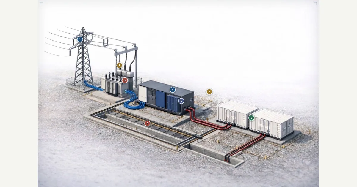 Interactive · bess.engineer ↗
 Key facts
| Control reference point | POI at the revenue meter, net of PCS/transformer/collector/aux losses |
|---|---|
| Loss + aux gap it must close | ~1-3 MW collector/transformer + ~0.5-2 MW aux on a 100 MW plant |
| Simultaneous P and Q budget | One apparent-power rating serves both: Q available = √(S² − P²) — a formula PE medium-voltage PCS datasheets print beside the power-factor row |
| Cost of the P/Q trade (fixed S) | Giving up 1% of rated P frees ~14% of rating as Q; 5% frees ~31%; 10% frees ~44% — arithmetic from S² = P² + Q², at the terminals and before losses |
| Nameplate is apparent power | One shipping MV PCS publishes AC output as a combined kVA/kW figure at cos φ = 1: 4,200 at 40 °C, 3,900 at 50 °C — the kW value holds only at unity power factor |
| MVA vs MW for ±0.95 pf | Rated MW and ±0.95 together need ~5.3% more apparent-power rating than MW; on a fixed nameplate, meeting ±0.95 instead costs ~5% of real power |
| P/Q priority is a setting | Which one yields at the apparent-power limit is configured, not physical; IEEE 1547-2018 and IEEE 2800-2022 treat it as agreed with the interconnecting entity, and it must match the interconnection study |
| Where the US reactive obligation sits | FERC Order 827: ±0.95 power factor at the high side of the generator substation for newly interconnecting non-synchronous resources; other markets name their own point and band, and neither travels |
| Fleet allocation | Proportional to each unit's remaining headroom and re-run as units clip — an even split saturates the hottest or lowest-SOC block first |
| Typical scan / execution cycle | ~50-200 ms |
| Typical P/Q closed-loop settling | ~1-5 s; fast frequency response 0.25-1 s |
| Typical POI regulation accuracy | ~1-2% of rated output (project-specific) |
| Frequency droop (common setting) | 3-5%, deadband ~±0.017 Hz in ERCOT up to the ±0.036 Hz maximum FERC Order 842 allows newly interconnecting generators elsewhere in the US (market-specific) |
| Ramp-rate limit (common utility spec) | ~10% of rated power per minute |
| Reactive capability (common spec) | ~0.95 leading/lagging power factor at POI |
| AGC signal update interval | ~2-6 s in most North American markets |
| Command precedence | Curtailment orders and POI export caps clamp everything beneath them; droop response adds to the dispatch setpoint rather than replacing it; the EMS/market schedule is the lowest-priority writer — the order belongs in the functional spec |
| Two paths off site | Real-time telemetry (DNP3 / IEC 60870-5-104) drives dispatch; the revenue meter drives settlement — different accuracy class and scan rate, so they disagree |
| Functional / interconnection standards | IEEE 1547, IEEE 2800, UL 1741 SB, IEC 61850; FERC Orders 827 and 842 + ISO/utility rules |
| Common protocols | DNP3 (IEEE 1815) / IEC 60870-5-104 to utility, ICCP/TASE.2 between control centers; Modbus TCP / IEC 61850 to PCS fleet |
| Distinct from | BMS (cell/rack protection), EMS (economic dispatch), SCADA (monitoring/control) |
The utility interface and the command stack
Upward, the demarcation is usually physical as well as logical. In North American practice the utility's remote terminal unit in the substation is the handoff, and the points list attached to the interconnection agreement — which measurements, which controls, at what scan rate — is a contract exhibit rather than a vendor choice. DNP3, standardized as IEEE 1815, and IEC 60870-5-104 are the usual protocols from the plant to the utility; ICCP/TASE.2 (IEC 60870-6) links control centers above that.
Two paths leave the site and they are not the same path: real-time telemetry drives dispatch and the operator's screens, while the revenue meter drives settlement, at a different accuracy class and a different scan rate. They will disagree, and the contract has to say which one governs which obligation. Common time alignment across both paths is what makes a disputed event reconstructible afterwards, which is why time synchronization is a commissioning item and not a footnote.
Several sources want to write the same P at once: the EMS schedule, an AGC signal, a utility curtailment order, the POI export cap in the interconnection agreement, and the plant's own frequency droop. These are not alternatives to pick between — they compose, and the composition rule belongs in the functional specification.
The usual ordering is that hard limits clamp everything beneath them, droop response is added on top of the dispatch setpoint rather than substituted for it, and the market or EMS schedule is the lowest-priority writer. Get that arithmetic backwards and the plant either acknowledges a curtailment instruction it then overrides, or answers a frequency event by abandoning its dispatch. Ask for the precedence table by name, and exercise each rung of it during commissioning rather than accepting it from the manual.
Why it matters in a real grid-scale project
The PPC is where interconnection compliance is physically enforced. Grid codes and the interconnection agreement specify reactive capability, voltage regulation, ramp-rate limits and frequency-response obligations measured at the POI; failing them can mean curtailment, penalties or denial of permission to operate.
Summing nominal inverter outputs without POI feedback overshoots or undershoots the contracted P and Q once losses and auxiliary load are counted. On a 100 MW plant, roughly 1-3 MW of collector and transformer loss plus 0.5-2 MW of auxiliary load is a routine multi-MW gap the PPC must close every cycle — the concrete reason plant control cannot be open-loop.
Commercially, the PPC is the interface that lets the asset earn revenue. Energy-market dispatch, ancillary-service products such as frequency regulation and reserves, and AGC signals land at the PPC and are translated into fleet setpoints; AGC updates arrive roughly every 2-6 seconds in most North American markets, and settlement compares the metered response against the command.
The controller's accuracy and latency directly drive regulation performance scores, mileage payments, and whether the plant passes the witnessed capability tests the utility requires before commercial operation. A slow or poorly tuned PPC leaves money on the table in every dispatch interval and can fail the test that unlocks market entry.
Typical values and standards
In North America the governing functional requirements come from IEEE 1547 for distribution-connected resources and IEEE 2800 for inverter-based resources connected at transmission level, alongside the FERC primary-frequency-response requirements of Order 842 and the applicable ISO/RTO and utility interconnection rules; UL 1741 SB certifies the grid-support functions in the PCS that the PPC commands.
IEC 61850 increasingly defines the communication and information model for plant control, and NERC CIP obligations shape how the controller is networked and secured. The PPC must implement the volt-var, volt-watt, frequency-watt and ride-through coordination these standards require, with settings that match exactly what the interconnection study modeled.
Envelope numbers a learner can carry: PPC scan and execution cycles typically run 50-200 ms; closed-loop P and Q regulation settles in roughly 1-5 seconds; POI regulation accuracy is commonly held within about 1-2% of rated output. Frequency droop is typically set at 3-5%, with deadbands running from about ±0.017 Hz in ERCOT to the ±0.036 Hz maximum FERC Order 842 allows newly interconnecting generators elsewhere in the US, and some fast-frequency products require full response within 0.25-1 second.
Ramp-rate limits near 10% of rated power per minute are a common utility requirement, and reactive capability to 0.95 leading/lagging power factor at the POI is a frequent baseline. Every one of these is project-specific — design to the executed interconnection agreement and witnessed test plan, never generic defaults.
How it shows up in specs, studies and contracts
In interconnection studies the PPC is the plant-level control block inside the positive-sequence (load-flow and dynamic) and EMT models the developer submits; the droop, deadband, ramp limits, voltage-control gains and P/Q priority entered there become binding, and later NERC MOD-026/MOD-027 verification expects the field settings to match that model.
On datasheets and single-line drawings it appears as a discrete plant-controller or PPC line item carrying a functional specification and a points list — which protocols, which registers, loop rates, failover behavior. Always check who actually supplies it: the PCS vendor, the BESS integrator, or a third-party controls house. Split scope across PPC, EMS and SCADA suppliers is a classic source of commissioning delay and finger-pointing.
In contracts and test reports the PPC drives the commissioning and capability-test plan, the ITP: witnessed P and Q capability at the POI, voltage and frequency-response tests, ramp tests and AGC signal-following runs — usually prerequisites for commercial operation and market qualification.
Concrete questions to ask any vendor: what is the control reference point and metering source; how is the plant target allocated across unequal converter blocks; what happens on loss of communication to the utility or to individual PCS units; what is the latency budget from market signal to POI response; and how are firmware and setting changes governed after the model is validated. The binding constraint is always the executed interconnection agreement plus witnessed test plan — an unmanaged setting change can void the study basis.
Common pitfalls
The most common field problem is control-loop interaction: the PPC's plant-level voltage or Q loop fighting the PCS units' own local control loops, producing slow oscillations or hunting at the POI. The fix is deliberate loop separation — fast inner loops in the inverters, a slower outer loop in the PPC — plus coordinated gain tuning during commissioning.
A second trap is fallback behavior: on loss of the utility link or the POI meter, the plant must fail to a safe, pre-agreed state such as holding the last setpoint, ramping to zero, or reverting to local voltage control, and that behavior must be written into the spec, not assumed on site. A third is discovering the P/Q priority setting during a witness test: at full real power the plant has no reactive room left, and which obligation gives way is a decision somebody should have made at study time.
Finally, do not treat PPC, EMS and SCADA as interchangeable labels. The energy management system decides the dispatch schedule against prices and state of charge, the PPC makes the plant track that at the POI within grid-code constraints, and SCADA provides visibility and operator control across everything.
When one vendor's brochure claims all three in one box, ask which functions are certified, which were modeled in the interconnection study, and which loop actually closes on the revenue meter — because the grid operator only sees, and only pays for, what happens at the POI. That distinction is what the whole compliance and settlement chain hangs on.
Common misconception
The PPC regulates output at the inverter terminals, so commanding each PCS to its setpoint delivers the contracted power at the grid.
In reality: The PPC regulates at the POI, not at the inverters. It continuously compensates for step-up and collector transformer losses, collector-cable losses, and station auxiliary load — routinely a multi-MW gap (order 1.5-5 MW on a 100 MW plant) — so the sum of inverter setpoints is deliberately offset from the POI target. Controlling only the inverters leaves the plant out of compliance at the metering point the grid operator actually settles against.
Visuals & further reading
- POI capability envelope Glossary
- MVA headroom Glossary
- Automatic Generation Control Glossary
- Control hierarchy Glossary
- Remote Terminal Unit Glossary
- P-Q capability test Glossary
- Telemetry Glossary
- BESS Commissioning: How a Container Full of Cells Becomes a Power Plant Article
- How Frequency Regulation Pays Batteries — and Why That Paycheck Shrinks Article
- Interactive: Plant Control Command Path Interactive visual · bess.engineer
- Interactive: Grid Support Functions Interactive visual · bess.engineer
- Interactive: PCS Control Loop Interactive visual · bess.engineer
- Interactive: Power Factor Triangle Interactive visual · bess.engineer
Power Plant Controller, in context.
The Grid-Scale BESS course covers power plant controller — and the rest of the system — from the ground up, the way it actually gets deployed.