Reactive power Q
Power & energy Essential term
Reviewed October 2026 by Sergey Syrvachev
Reactive power (Q) is the component of AC power that oscillates between source and grid without transferring any net energy over a cycle. It is measured in volt-amperes reactive (VAr), or MVAr at grid scale. In a battery energy storage system the power conversion system (PCS) generates or absorbs Q electronically to push voltage at the point of interconnection (POI) up or down, independent of the real power (P) the batteries move.
P and Q combine in quadrature into apparent power (S = √(P² + Q²)); it is S, not P, that sets the MVA limit of the inverters and transformer. You first meet Q as a power-factor line in the interconnection agreement and a P-Q curve on the datasheet.
Back to the free route: Electrical foundations — no cost, no account.
What it is (precise)
When current and voltage are out of phase, part of the AC waveform delivers energy (real power, P, in MW) and part simply sloshes between the grid's inductances and capacitances. That sloshing component is reactive power. Injecting Q (over-excited or capacitive mode) tends to raise local voltage; absorbing Q (under-excited or inductive mode) tends to lower it. Q is the lever grid operators use to hold voltage, and because it costs current-carrying capacity, every VAr competes for the same MVA the plant uses to export MW.
In a grid-scale BESS the batteries never make Q — the cells store and return only real energy. Q is synthesized electronically by the PCS inverters, so a station can supply or sink VArs even at zero real power output. The three link as S = √(P² + Q²), with power factor PF = P/S = cos φ measuring how much apparent power does real work. A memorable anchor: holding PF 0.95 means Q is about a third of P — roughly 0.33 MVAr per MW — and costs only about 5% extra MVA.
Sign and reference point both matter. In the generator convention used for interconnection work, positive Q means injecting VArs (over-excited, supporting voltage) and negative Q means absorbing them. A modern BESS runs in all four quadrants of the P-Q plane: it can inject or absorb Q whether it is charging or discharging MW. Location matters as much as sign — grid codes state Q obligations at the POI, while inverter datasheets state capability at the machine terminals, with transformers and cables in between.
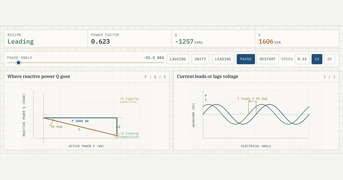 Interactive · bess.engineer ↗
 Numbers
Key facts
| Symbol / unit | Q — volt-amperes reactive (VAr); MVAr at grid scale |
|---|---|
| Core relationship | S = √(P² + Q²); PF = P/S = cos φ |
| Typical grid-code PF range | approx. 0.95 leading to 0.95 lagging at rated output |
| Cost of PF 0.95 in MVA | only approx. 5% extra apparent power (approx. 105 MVA per 100 MW) |
| Q at PF 0.95, 100 MW plant | approx. 33 MVAr (S approx. 105.3 MVA) — memorize approx. 0.33 MVAr per MW |
| European grid codes | Q/Pmax typically approx. 0.30-0.35 at rated output |
| IEEE 1547 Category B (distribution) | inject/absorb on the order of 44% of nameplate apparent rating |
| Source of Q in a BESS | PCS inverters (four-quadrant), not the battery cells |
| Sign convention (generator) | Q > 0 = injecting / over-excited (raises voltage); Q < 0 = absorbing (lowers it) |
| Transformer reactive consumption | typical impedance approx. 6-8% on unit base (up to ~10% for larger units); MVAr draw rises with the square of loading |
| Binding sizing corner | max load + min voltage + max ambient at the POI — not the nominal point |
| Key references | FERC Order 827, IEEE 2800 (transmission IBRs), IEEE 1547 (distribution), plus ISO/utility curves |
Typical values and standards
Watch the units: VAr / MVAr for Q, VA / MVA for S, W / MW for P. A common design target is full reactive capability at PF 0.95 at rated MW — about 0.33 MVAr per MW — and many modern grid codes additionally require Q at reduced or even zero active power, which defines the inverter's four-quadrant P-Q capability curve. European connection codes typically ask for a Q/Pmax ratio around 0.30 to 0.35 at rated output.
The governing documents are interconnection-specific and each has a distinct role.
In North America, FERC Order 827 requires new non-synchronous resources to provide roughly 0.95 leading to 0.95 lagging at the high-side POI; IEEE 2800 sets reactive-capability and voltage-control performance for transmission-connected inverter-based resources, including capability at zero active power; and IEEE 1547 governs distribution-connected systems, whose Category B performance calls for injecting and absorbing on the order of 44% of nameplate apparent rating. Each ISO or utility then layers its own voltage-support curves on top.
Hardware numbers frame what is achievable. Utility-scale PCS blocks are typically about 1 to 5 MVA each, and their Q capability is voltage-dependent: injecting VArs into an already-high grid voltage pushes the inverter against its current and DC-bus limits, so capability curves shrink near the voltage extremes and at high ambient temperature.
Between the inverters and the POI, medium-voltage transformers with typical impedances of roughly 6 to 8% on the transformer's own base (up to ~10% for larger units) consume MVArs under load, rising with the square of loading, while MV collector cables generate capacitive MVArs at light load.
In practice
Why it matters in a real grid-scale project
Grid codes almost universally require a BESS to provide reactive power and voltage support at the POI, typically across a power factor range of roughly 0.95 leading to 0.95 lagging at rated output. Meeting this is a condition of the interconnection agreement, so the requirement directly drives equipment sizing: the PCS and the medium-voltage transformer must be rated in MVA to deliver full Q while still exporting the contracted MW. Under-size the MVA and the plant physically cannot meet its grid-support obligation.
Reactive power also carries a commercial cost: it consumes inverter and transformer headroom and adds I²R losses in the collector system, yet it often earns separate ancillary-service or voltage-support revenue. Engineering teams trade the MVA reserved for Q against the MW available for energy arbitrage, and must account for cable, transformer, and auxiliary-load reactive demand so the net Q delivered at the POI — not at the inverter terminals — still lands on the grid-code curve.
The arithmetic is unforgiving because Q enters the MVA budget in quadrature. Delivering 100 MW at PF 0.95 needs about 105.3 MVA carrying roughly 32.9 MVAr. But if the utility specifies a fixed MVAr quantity, or dynamic voltage support when current limits bind, the required inverter count can grow well beyond what the nameplate MW alone suggests. This is why utility-scale plants are quoted and studied in MVA, not MW: S, not P, is the ceiling.
How it shows up in specs, studies and contracts
On a PCS datasheet, reactive capability appears as a P-Q capability chart or a table of kVA versus AC voltage and temperature — never trust a single kVAr number. The vendor questions to ask are concrete: what is the Q limit at minimum and maximum AC voltage, at my site's design ambient, and at P = 0? Some inverters need a standby or STATCOM-style mode to make VArs at night. Pull the transformer datasheet too: its MVA rating and impedance decide how much inverter Q survives to the POI.
In interconnection studies, Q drives the power-flow and dynamic cases: the study models the plant's full reactive envelope, verifies the voltage schedule holds across contingencies, and usually obligates automatic voltage regulation through the plant controller. In contracts and market rules, read for four things — the required power factor range, its reference point (POI versus terminals), whether capability must be dynamic or may be met with switched shunts, and whether VArs are compensated. Some markets pay for voltage support; most treat it as a free obligation you still engineer for.
During commissioning, expect reactive-capability tests: the utility witnesses the plant injecting and absorbing its declared Q at several MW points, measured at the POI meter. The working engineer's checklist is short and repeatable: confirm the required Q at the POI in MVAr, not just a power factor; translate it back through transformer and collector losses to a per-inverter target; verify the PCS curve covers that target across voltage and temperature; and confirm zero-MW VAr capability if the code demands it. If any step fails at the worst corner, add MVA.
Pitfalls
Common pitfalls
The classic error is sizing to nameplate MW at the inverter terminals, then failing the POI requirement at the interconnection study. Transformer reactive consumption rises with the square of loading, so a plant that holds PF 0.95 at 50% output can fail it at 100%. The fix is a proper reactive-power balance from cells to POI evaluated at the worst corner — maximum load, minimum voltage, maximum ambient — not the comfortable typical case that leaves a shortfall discovered only after the hardware is bought.
Terminology is the second trap. Leading versus lagging power factor confuses engineers because the labels flip between the load and generator conventions; always restate interconnection paperwork as inject or absorb MVArs at the POI. And never conflate an MVA rating with a MW rating: a 105 MVA PCS lineup is not a 105 MW plant. Quoting apparent power as real power overstates the business case while doing nothing to shrink the Q obligation the plant still owes.
Common misconception
The batteries themselves supply reactive power, so VAr capability comes from the cells (and a bigger battery buys you more Q).
In reality: LFP (or NMC) cells store and return only real energy. Reactive power is synthesized electronically by the PCS inverters, which is why a BESS can inject or absorb Q even at zero state-of-charge change or zero MW output. The binding limit on Q is inverter and transformer MVA, not battery capacity — so you buy more reactive headroom by adding MVA, not MWh.
Go further
Visuals & further reading
- Interactive: Reactive Power Triangle Interactive visual · bess.engineer
- Interactive: Power Factor Triangle Interactive visual · bess.engineer
- Interactive: Grid Support Functions Interactive visual · bess.engineer
Reactive power, in context.
The Grid-Scale BESS course covers reactive power — and the rest of the system — from the ground up, the way it actually gets deployed.