Power factor PF
Reviewed August 2026 by Sergey Syrvachev
Power factor (PF) is the ratio of real power P to apparent power S, equal to cos φ, where φ is the phase angle between voltage and current. It is dimensionless, between 0 and 1, and signed leading or lagging. For a grid-scale BESS it describes the operating point of the power conversion system at the point of interconnection (POI): how much of the plant's MVA capability is delivered as usable MW versus committed to reactive power.
A typical interconnection requirement is continuous operation from 0.95 leading to 0.95 lagging at the POI. Two qualifiers belong with every PF figure and are missing from most of them: the plane it is measured at, and the convention that gives leading and lagging their meaning.
Back to the free route: Electrical foundations — no cost, no account.
What it is (precise)
For a three-phase plant, apparent power S (kVA or MVA) is the vector sum of real power P (kW or MW) and reactive power Q (kVAr or MVAr): S = √(P² + Q²). Power factor is PF = P/S = cos φ. At unity PF (1.0) the inverter delivers only real power and Q is zero; at 0.95 PF, reactive power equals about 33% of the real power being delivered (tan φ ≈ 0.329), and at 0.90 PF it reaches about 48%.
Because Q grows quickly as PF drops, small PF changes have outsized equipment impact. Read the ratio both ways: from a converter rating, P = S × PF; from a real-power obligation, S = P / PF — 1.053 MVA per MW at 0.95 PF, 1.111 at 0.90 and 1.250 at 0.80, with displacement angles of 18.2°, 25.8° and 36.9°, so a typical interconnection's whole reactive obligation lives inside a cone under twenty degrees wide.
Under the common generator convention, a lagging (over-excited) PF means the plant supplies reactive power, acting as a source of Q like a capacitor bank, while a leading (under-excited) PF means it absorbs reactive power. A battery PCS is a four-quadrant device: it can source or sink both P and Q, so PF is defined during both charge and discharge, across the full reactive range the inverter control supports.
Many modern PCS can even exchange Q at zero real power, operating as a STATCOM while the battery idles. PF's structural weakness as a control variable is that cos φ is even — cos(+18.2°) and cos(−18.2°) are both 0.95 — so the ratio alone cannot say which way the VARs move; direction must travel beside it as a word or a sign, and those words flip between load and generator convention, which is the sign-convention entry's subject. State Q in MVAr with an explicit inject or absorb and the ambiguity is gone.
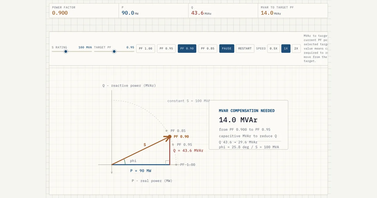 Interactive · bess.engineer ↗
 Measurement boundary, and where the ratio stops being defined
PF is a ratio of two flows at one plane, and it changes as you walk the single line. The MV step-up transformers and the collection cables trade in reactive power in opposite directions: series reactance consumes VARs in proportion to the square of the current through it, while cable capacitance generates them largely regardless of loading.
The PF at the POI and the PF at the inverter terminals are therefore different numbers at the same instant, and the gap moves with plant output — a lightly loaded collection system can sit net capacitive while the fleet runs near unity, then swing inductive at full discharge. Which plane the obligation names is load-bearing, and the standards below give the US answer. The plant controller closes its loop on POI feedback and asks the fleet for whatever terminal-level Q makes the POI number correct, so the PCS routinely runs at a power factor the agreement never names.
PF is P/S, so at zero real power any reactive output at all reads PF = 0 — the ratio collapses to a single value and stops distinguishing anything, and with P and Q both zero it is 0/0. Either way a clause reading 0.95 PF at all outputs says nothing at the bottom of the range, which is exactly where a BESS parked at zero P is still expected to hold voltage.
Codes written with storage in mind state the requirement in MVAr, or as a percentage of rated MVA, at zero and at partial output. The other edge is at the top, where cos φ is flat and resolves reactive flow badly: a PF of 0.99 still commits Q equal to about 14% of P, so the step from 1.00 to 0.99 on a meter display is a seventh of the plant's real power reappearing as reactive current. Near unity, specify MVAr.
Numbers
Key facts
| Definition | PF = P/S = cos φ; S = √(P² + Q²) |
|---|---|
| Range | 0 to 1.0 (unity), signed leading or lagging |
| Typical grid-code PF range at POI | 0.95 leading to 0.95 lagging (sometimes 0.90) |
| Real-power impact at 0.95 PF | 100 MVA PCS delivers ~95 MW + ~31 MVAr |
| Real-power impact at 0.90 PF | 100 MVA PCS delivers 90 MW + ~44 MVAr |
| Q as share of P | ~33% at 0.95 PF; ~48% at 0.90 PF; ~14% even at 0.99 PF |
| MVA per MW of obligation | S = P/PF: 1.053x at 0.95 PF; 1.111x at 0.90; 1.250x at 0.80 |
| Displacement angle | 18.2° at 0.95 PF; 25.8° at 0.90; 36.9° at 0.80 |
| Sign convention | Lagging = over-excited = supplies Q; leading = under-excited = absorbs Q |
| Why the number needs a direction flag | cos φ is even: +18.2° and −18.2° both read 0.95, so PF alone cannot show Q direction |
| Where the definition ends | At P = 0 the ratio reads 0 for any Q at all, and 0/0 only for none — it stops distinguishing anything; specify Q in MVAr or % of rated MVA at zero and partial output |
| Measurement plane | POI PF ≠ inverter-terminal PF; transformer and collector-cable vars shift it with loading |
| US reactive-capability rules | FERC Order 827 (2016); IEEE 1547-2018 (distribution), IEEE 2800-2022 (transmission) |
| Datasheet PF ranges | PE Freemaq PCSK/PCSM 0.5 lead to 0.5 lag; EPC CAB1000 (3L.2) 0.8-1; SMA Sunny Central UP cos φ to 0.0 over-/under-excited |
| Worked datasheet pair | SMA SC 2800 UP-US at 35 °C: 2,800 kVA at cos φ = 1, 2,240 kW at cos φ = 0.8 |
| PCS behaviour | Four-quadrant: ±P and ±Q; many modern units also hold Q at zero real power (STATCOM mode), where the DC bus stays energised and the controls allow it |
| Derating drivers | Low DC voltage (low SOC), high ambient, altitude, off-nominal AC voltage |
| Displacement vs true PF | True PF includes harmonics; harmonic limits sit under IEEE 519 in US practice |
| Sizing rule | Rate and procure the PCS in MVA, not MW |
Typical values and standards
The most common transmission-level requirement is continuous capability from 0.95 leading to 0.95 lagging at the POI at full output, with some interconnections specifying 0.90 or a full reactive-capability (D-curve) envelope that varies with real-power output and grid voltage. In the United States, FERC Order 827 (2016) requires newly interconnecting non-synchronous resources, including storage, to provide dynamic reactive capability across 0.95 leading to 0.95 lagging measured at the high-side of the generator substation transformer.
IEEE 1547-2018 defines reactive and voltage-support functions for distribution-connected resources, and IEEE 2800-2022 does the same for transmission-connected inverter-based resources; the transmission operator's or ISO/RTO's interconnection requirements set the binding envelope for a given project.
PCS datasheets quote a nameplate in kVA at a stated reference ambient (often 40-50 °C; SMA states the Sunny Central UP family at 35 °C) and a PF range beside it, wider than any grid code asks: Power Electronics' Freemaq PCSK and PCSM families list 0.5 leading to 0.5 lagging with reactive injection at night, EPC's CAB1000 (3L.2) lists 0.8 to 1 leading and lagging, and SMA's Sunny Central UP quotes displacement cos φ adjustable from 0.0 over-excited to 0.0 under-excited.
That same SMA sheet prints the conversion as two rated rows for the SC 2800 UP-US at 35 °C: 2,800 kVA at cos φ = 1, and 2,240 kW at cos φ = 0.8.
The range does not describe the usable envelope, which shrinks with low DC-link voltage (low state of charge), high ambient temperature, altitude and off-nominal AC voltage. Displacement PF (cos φ of the fundamental) is also distinct from true PF, which includes harmonic distortion; for modern grid-following BESS inverters the two are close, and harmonic current limits are governed separately, under IEEE 519 in US practice.
All of these electrical ratings are independent of the safety standards (UL 9540 system certification, UL 9540A fire-propagation test method, NFPA 855 installation standard) that apply to the same equipment.
In practice
Why it matters in a real grid-scale project
Reactive capability is contracted, not free. Operating away from unity PF means a fixed PCS rating in MVA buys fewer MW, because apparent power is the binding limit of the inverter. A plant with 100 MVA of PCS that must hold 0.95 PF at the POI can deliver only about 95 MW of real power, with the remaining headroom committed to roughly 31 MVAr; at 0.90 PF the same hardware delivers 90 MW with about 44 MVAr reserved. This directly drives how many PCS blocks (typically ~1-5 MVA each), containers and transformers are installed, so PF is a first-order sizing and capital-cost variable.
Grid codes and interconnection agreements mandate the PF or reactive-capability envelope at the POI, and reactive dispatch (voltage control, Q control, power-factor control or volt-var droop) is a continuous operational duty, not an occasional event. Underestimating reactive duty leads to undersized PCS, transformer and cable thermal margins, or forces curtailment of real power to free apparent-power headroom.
From the procurement side the same division sets the order: a 100 MW obligation at 0.95 PF needs at least 105.3 MVA of converter before any allowance for transformer and cable var consumption, ambient derating, or a block out of service. The chord that gap is measured along belongs to the MVA-headroom entry.
How it shows up in specs, studies and contracts
On a PCS datasheet, look for the kVA or MVA rating, the stated PF range, and the P-Q capability curves at several DC voltages and temperatures — a single-number rating hides the derating that matters.
In the interconnection study and the large generator interconnection agreement (LGIA or regional equivalent), find the reactive-capability requirement, the measurement point, and whether the envelope must be met at full output only or across the whole output range including charging. Energy contracts and capacity tests are written in MW and MWh at the POI, so the reactive obligation has to be translated into installed MVA before anyone commits to a nameplate real-power figure.
Questions worth asking on every project: must reactive capability be available at zero real power and during charging; how many MVAr does the study assign to the step-up and main power transformers at full load; and does the plant controller's volt-var mode or PF mode match what the operating agreement assumes? Commissioning test reports should demonstrate the reactive envelope at the corners (full P with max lagging Q, full P with max leading Q), and the answers determine whether the PCS fleet needs 5-15% more MVA than the contracted MW.
Pitfalls
Common pitfalls
The classic trap is quoting the plant in MW and sizing in MW. The PCS and transformers are apparent-power machines, rated and thermally limited in MVA; the MW obligation plus the reactive envelope, plus collection-system and transformer reactive losses, set the required MVA. A second trap is leaning on the words "leading" and "lagging" instead of stating Q direction explicitly as over-excited/under-excited or inject/absorb. Duration and usable energy are unaffected by PF, but the MW half of any MW/MWh statement is not.
Finally, do not conflate PF with efficiency. A plant at 0.9 PF is not "losing 10%" of anything; reactive power is exchanged, not dissipated, though the extra current it drives does increase I²R losses slightly and consumes thermal capacity.
Household intuition from consumer electronics or EV chargers, where PF correction is about cleaning up rectifier current draw, does not transfer: in a utility-scale BESS, reactive capability is a deliberately dispatched grid service with contractual value, sometimes separately compensated, and always a constraint on how much real power the installed hardware can deliver.
Common misconception
A BESS rated at 100 MW can always deliver 100 MW regardless of the required power factor.
In reality: The PCS is limited by apparent power (MVA). Holding a non-unity PF such as 0.95 consumes apparent-power headroom for reactive power, so real-power output drops to about 95 MW unless the equipment is oversized in MVA to meet both the MW obligation and the reactive envelope.
Go further
Visuals & further reading
- Interactive: Power Factor Triangle Interactive visual · bess.engineer
- Interactive: Phase Shift and Power Interactive visual · bess.engineer
- Interactive: Reactive Power Triangle Interactive visual · bess.engineer
- Reactive power Glossary
- Apparent power Glossary
- P-Q capability Glossary
- MVA headroom Glossary
- POI capability envelope Glossary
- Sign convention Glossary
- Measurement boundary Glossary
- Phase angle Glossary
- BESS sizing: MW, MWh, degradation and augmentation Article
Power factor, in context.
The Grid-Scale BESS course covers power factor — and the rest of the system — from the ground up, the way it actually gets deployed.