Apparent power S
Power & energy Essential term
Reviewed October 2026 by Sergey Syrvachev
Apparent power (S) is the total power a power conversion system (PCS) or transformer must physically handle, equal to the vector combination of real power (P, in MW) and reactive power (Q, in MVAr) through the relation S = √(P² + Q²). It is measured in volt-amperes — VA, kVA, or MVA at grid scale.
Because every PCS, medium-voltage collector, and main power transformer is rated in MVA, apparent power — not MW alone — is the true sizing limit of a grid-scale BESS export interface and the quantity grid codes police at the point of interconnection. You meet S first as a datasheet kVA line, then again in every interconnection study.
Back to the free route: Electrical foundations — no cost, no account.
What it is (precise)
A grid-connected BESS does two electrical jobs at once: it moves real power P (the MW that actually charge or discharge the battery) and it supplies or absorbs reactive power Q (the MVAr that props up or pulls down grid voltage). Apparent power S is the magnitude of the combined current the PCS pushes through its switches, cables, and step-up transformer — it is what the hardware physically carries, regardless of how the flow splits between P and Q. In a three-phase system S = √3 × V(line-line) × I(line), which is why S, not P, sets conductor sizes, breaker frames, and winding ratings.
The three quantities form a right triangle: S² = P² + Q², and the power factor PF = P/S = cos φ is the cosine of the angle between them. At unity power factor (Q = 0) the system runs at S = P, so a 100 MW dispatch needs 100 MVA. Ask the same PCS to also deliver reactive power and S climbs above P even though the battery's MW output has not changed. Apparent power exists only on the AC side of the plant; the DC bus between racks and PCS carries real power only, so S is defined from the inverter terminals outward — an AC / DC boundary worth fixing firmly in your mental model.
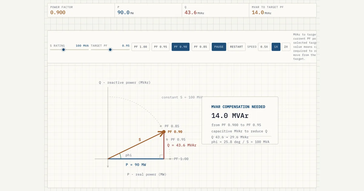 Interactive · bess.engineer ↗
 Where it sits in the system
Keep the two rating families separate. Energy quantities — nameplate MWh, usable energy, duration (energy divided by power), and C-rate — describe the battery's energy: how much charge it holds and how fast it can move. Apparent power is a purely AC-side power rating: it says nothing about MWh or how many hours the plant can run. A 100 MW / 400 MWh (4-hour, 0.25C) system and a 100 MW / 200 MWh (2-hour) system can share the identical PCS and MVA export interface, because S is fixed by P, Q, and the inverter rating, not by the energy behind it.
That split is why sizing has two independent axes. The energy axis sets rack count, container count, and duration; the power axis sets PCS block count and transformer MVA. Apparent power lives on the power axis. When a spec says 'MW' it is naming P at some assumed power factor; the hardware underneath is always sized in MVA, and the gap between the two is exactly the reactive headroom the plant is contracted to hold. Confusing the axes — reading MVA as if it bounded energy, or MW as if it bounded the inverter — is the single most common student error on this term.
Numbers
Key facts
| Unit | VA / kVA / MVA (volt-amperes) — a power rating, never energy (MWh) |
|---|---|
| Defining relation | S = √(P² + Q²); PF = P/S = cos φ |
| Three-phase formula | S = √3 × V(L-L) × I(line) |
| Typical grid-code PF range | ~0.95 lagging to 0.95 leading at POI (FERC Order 827) |
| MVA headroom over MW at 0.95 PF | +5.3% minimum (S = P/0.95); ~5-15% in practice with losses and derating |
| Typical central PCS block rating | ~1-5 MVA per block (string inverters: hundreds of kVA) |
| Datasheet reference conditions | kVA typically quoted at 40-45 °C ambient, up to ~1000 m altitude |
| What it rates | PCS / inverter blocks, MV collector, and the main power transformer |
| Where S exists | AC side only — the DC bus between racks and PCS carries real power |
| Independent of energy axis | Same MVA serves a 2h or 4h plant; duration, C-rate and usable energy set separately |
| Relevant standards | FERC Order 827, IEEE 1547-2018, IEEE 2800-2022, IEC 62933 |
| Capability curve shapes | Semicircle (constant S) vs rectangular P-Q envelope — affects Q at full P |
Typical values and standards
Grid codes and interconnection agreements typically mandate continuous operation across roughly 0.95 lagging to 0.95 leading power factor at the POI. In the US, FERC Order 827 imposes that 0.95 dynamic range on newly interconnecting non-synchronous generators; IEEE 1547-2018 sets reactive capability categories for distribution-connected resources; IEEE 2800-2022 covers transmission-connected inverter-based resources; and IEC 62933 frames the storage system itself.
At PF 0.95, apparent power is P / 0.95 — about 5.3 percent more MVA than MW — before losses and derating, and real projects commonly land 5 to 15 percent above the MW figure once those are counted.
Hardware anchors to memorize: utility-scale central PCS blocks run on the order of 1 to 5 MVA each (string inverters at hundreds of kVA), fed from DC buses up to 1500 VDC, with medium-voltage step-up from 400 to 800 V AC output to 33 or 34.5 kV collectors.
Datasheet kVA is usually stated at 40 or 45 degrees C ambient and up to about 1000 m altitude; beyond those points the ceiling typically derates a few percent per additional 5 degrees C or per few hundred metres. A nominally 3.6 MVA block can behave as a 3.2 MVA block on a hot afternoon at elevation — the number an interconnection study holds you to, not the headline.
In practice
Why it matters in a real project
PCS modules, inverter blocks, the medium-voltage collector, and the main power transformer are all rated in MVA (or kVA per inverter), not MW. If interconnection terms require the plant to hold, say, 0.95 leading-to-lagging power factor at the point of interconnection (POI), the export interface must be oversized in apparent power to deliver full MW while simultaneously sourcing or sinking the required MVAr.
Size only for MW and the plant either trips on overcurrent or cannot meet its reactive obligations during a voltage event. Apparent-power headroom drives the count and rating of PCS units and the MVA of the transformer, so it is a direct line item on the single-line diagram.
The commercial stakes are asymmetric. Energy revenue is settled on delivered MWh of real power, but the interconnection agreement is enforced on the reactive envelope — so MVA bought purely for Q capability earns nothing directly yet is non-negotiable.
Developers respond by specifying PCS blocks with kVA ratings typically 5 to 15 percent above the contracted MW share, or by choosing units whose capability curve is a full semicircle (constant S) rather than a rectangle, so one block covers both the MW target and the PF corner points. Sizing tools therefore evaluate the worst-case point on the P-Q capability curve, not just nameplate MW, and net out the temperature, voltage, and altitude derating that erodes the inverter's apparent-power ceiling.
How it shows up in specs, studies and contracts
On a PCS datasheet, find the rated apparent power in kVA together with its reference conditions — ambient temperature, altitude, AC voltage window, and power factor range — and the P-Q capability diagram that shows whether full Q is available at full P. On the transformer spec, confirm the ONAN/ONAF MVA stages cover aggregate PCS output at the worst-case reactive point, not just plant MW.
Interconnection studies model reactive capability at the POI, and the resulting range is written into the interconnection agreement as a binding obligation; capacity-test and commissioning reports then have to demonstrate the four corner points of the P-Q envelope on site.
Questions to ask, in order: is the quoted figure kVA or kW, and at what temperature and altitude? Is reactive capability required at zero real power (standby VAr support), which some grid codes demand and some PCS firmware caps? Does the plant controller run P-priority or Q-priority when the S limit binds during a voltage excursion?
Is the PF obligation measured at the inverter terminals or the POI meter — a gap worth several percent of MVA? What trips people is treating datasheet MVA as guaranteed POI capability; size instead from the POI obligation backwards — required P and Q at the meter, plus losses and derating — verified against the vendor's curves at the site's design ambient.
Pitfalls
Common misconception
A 100 MW BESS needs only a 100 MVA PCS and transformer.
In reality: Only at unity power factor. The moment the plant must source or sink reactive power to meet a grid-code PF range (e.g. 0.95), apparent power exceeds the MW figure (S = P/0.95 ≈ 105 MVA before losses, often 105-115 MVA in practice), so the PCS and transformer are sized in MVA with reactive headroom — not in MW alone. MVA also says nothing about MWh, duration, or C-rate: those are set independently on the DC energy side.
Go further
Visuals & further reading
- Interactive: Power Factor Triangle Interactive visual · bess.engineer
- Interactive: Phase Shift and Power Interactive visual · bess.engineer
- Interactive: Reactive Power Triangle Interactive visual · bess.engineer
Apparent power, in context.
The Grid-Scale BESS course covers apparent power — and the rest of the system — from the ground up, the way it actually gets deployed.