AC / DC
Reviewed October 2026 by Sergey Syrvachev
AC (alternating current) is the form of electricity on the grid side of a battery energy storage system: voltage and current reverse direction 50 or 60 times per second. DC (direct current) is the form inside the battery, flowing one way at a voltage set by state of charge.
A grid-scale BESS stores energy as DC in its cells and converts between the two domains through the power conversion system (PCS): DC-to-AC when discharging, AC-to-DC when charging. Nearly every rating, loss and contractual number is defined on one specific side of that boundary, so the first skill is knowing which side a number is quoted on.
Back to the free route: Electrical foundations — no cost, no account.
What it is (precise)
At the cell and rack level a stationary BESS is pure DC, and this is where energy is physically stored. Lithium-iron-phosphate (LFP) cells, the dominant chemistry in utility-scale storage, sit near 3.2 V each and series-connect into modules and racks to build a DC bus that typically runs up to ~1500 VDC, with 2000 V architectures now emerging. That bus carries one-directional current whose voltage drifts with state of charge: higher when full, lower when depleted. There is no frequency, no phase and no reactive power on the DC side — those concepts simply do not exist there.
The PCS is the only place the two domains meet: a bidirectional converter that synthesizes a 50/60 Hz waveform from the DC bus by pulse-width modulation when discharging, and rectifies grid AC into controlled DC charging current the rest of the time. Its AC terminals are low-voltage three-phase, typically 400–800 V; a medium-voltage transformer then steps this up to 13.8–34.5 kV. Memorize the full energy path, because every spec sits somewhere on it: DC cells to DC bus to PCS to LV AC to MV transformer to AC collection to the point of interconnection (POI).
Why it matters in a real grid-scale project
The AC/DC boundary is where almost every meaningful rating and loss lives. Energy is stored and warranted in DC terms — DC nameplate MWh at beginning of life — but the plant is sold, dispatched, metered and penalized in AC terms at the POI. Each conversion pass costs a few percent: a typical stack loses roughly 1.5–3% in the PCS, 0.5–1% in the transformer, and 1–3% to auxiliaries. Those losses, on top of the usable SOC window, are why AC energy at the POI falls below DC nameplate — a gap that sets capacity payments, performance guarantees and liquidated damages.
The boundary also fixes plant architecture. In a DC-coupled design (common where solar shares the site) PV and battery share one DC bus behind a single inverter; in an AC-coupled design each asset carries its own PCS. Everything the grid code demands — real power, voltage and frequency response, power factor at the POI — is an AC-side quantity produced by PCS control. That is why the converter and transformer are rated in apparent power, quoted in MVA rather than MW: a 100 MVA block delivers less real power once it must also supply reactive current, following S² = P² + Q².
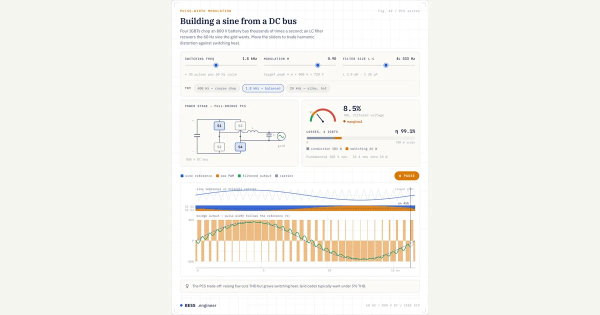 Interactive · bess.engineer ↗
 Key facts
| DC side | One-directional current; LFP cells ~3.2 V; bus up to ~1500 VDC (2000 V emerging); no frequency, phase or reactive power |
|---|---|
| AC side | Grid-synchronous 50/60 Hz; LV 400–800 V at inverter, stepped to 13.8–34.5 kV MV collection |
| Boundary device (PCS) | Bidirectional inverter, ~1–5 MVA per block, rated in apparent power (MVA) — not MW |
| Single-pass losses | PCS ~1.5–3%; MV transformer ~0.5–1%; auxiliaries ~1–3%; one-way chain ~95% |
| Round-trip efficiency | High-80s to low-90s % AC-to-AC incl. auxiliaries; RTE ≈ one-way² (95% one-way ≈ 90% RTE) |
| DC vs AC energy | DC nameplate typically ~5–15% above AC deliverable energy |
| Duration reference | Quoted AC at POI: 100 MW / 400 MWh = 4 h at 0.25C; most plants 2–4 h. C-rate is DC-side, cell-referenced |
| Coupling architectures | DC-coupled = shared DC bus, one inverter; AC-coupled = one PCS per asset |
| AC-side standards | UL 1741 (inverter), IEEE 1547 (distribution interconnection), IEEE 2800 (transmission IBR) |
| DC-side standards | UL 1973 (cell to rack), IEC 62619 (industrial lithium cells and batteries — international counterpart) |
| System-level standards | UL 9540 (ESS safety cert) ≠ UL 9540A (fire-propagation test → NFPA 855); NFPA 68/69 (deflagration) |
| Contract checklist | Confirm bus, nameplate-vs-usable, BOL-vs-EOL, which aux loads are in the RTE, and loss ownership to the meter |
Typical values and standards
Representative numbers for a modern plant: DC bus up to ~1500 VDC (2000 V emerging); PCS blocks of roughly 1–5 MVA each; LV AC output 400–800 V; MV collection at 13.8–34.5 kV. A good PCS peaks near 98–99% at rated load but falls off sharply below about 20% load, and the MV transformer adds another 0.5–1%. One-way efficiency of the whole chain lands near 95%, which squares to a round-trip efficiency in the high-80s to low-90s percent once auxiliaries count. Keep the rule handy: round-trip efficiency ≈ one-way², so 95% one way is ~90% round trip — never the 95%+ a cell vendor advertises.
Because of those losses plus the usable state-of-charge window and degradation allowances, DC nameplate energy is typically oversized to about 5–15% above the AC deliverable energy the offtaker sees. Duration is quoted at the POI in AC terms: a 100 MW / 400 MWh AC plant is a 4-hour system running at 0.25C, and most utility-scale projects sit in the 2–4 hour band, trending longer. Watch the reference frame, because C-rate is a DC-side, cell-referenced number (power divided by energy) while the duration in a contract is almost always AC at the POI.
Standards split cleanly across the boundary. On the AC side, UL 1741 certifies the inverter, IEEE 1547 governs distribution-level interconnection, and IEEE 2800 sets performance for transmission-connected inverter-based resources. On the DC side, UL 1973 covers the battery from cell to pack and rack and IEC 62619 covers industrial lithium cell and battery safety internationally.
Spanning both: UL 9540 is the safety certification for the ESS as a whole, while UL 9540A is a separate fire-propagation test method whose data feeds NFPA 855, the installation standard — never treat the two 9540 marks as interchangeable. NFPA 68/69 address deflagration venting and prevention for enclosures.
How it shows up in specs, studies and contracts
On a datasheet, the battery container is specified in DC terms — nameplate MWh, DC voltage window, C-rate limits — while the PCS is specified in kVA or MVA at a stated AC voltage and ambient temperature. That AC rating derates with temperature, altitude and grid voltage, so identical hardware delivers different numbers at different sites.
Ask any vendor three questions: which side of the boundary is this number on, at what reference conditions, and is the quoted efficiency a peak or a weighted average over a real dispatch profile. The headline efficiency is almost always the peak, not what you will meter.
In interconnection studies and market registration, only the AC side exists: POI capacity, reactive capability and ride-through are what the utility models and what a capacity market accredits, so the binding constraint is the AC number, not the DC nameplate.
Revenue metering sits at or near the POI, so auxiliary consumption and transformer losses fall inside your losses, not the grid's. In any energy model, state where each efficiency is applied — a round-trip efficiency quoted DC-to-DC at the battery terminals is not interchangeable with one quoted AC-to-AC at the POI, and mixing them overstates delivered energy.
In contracts, capacity and efficiency tests run at a defined AC measurement point, while battery warranties are usually written against DC energy throughput or cycle count at reference conditions.
Before signing, pin down five things: at which bus each guarantee is measured, whether guaranteed energy is nameplate or usable, beginning-of-life or end-of-life, which auxiliary loads sit inside the round-trip number, and who owns the losses between the battery terminals and the revenue meter. Most disputes over missing megawatt-hours trace back to one of these definitions — the physics is usually fine; the two parties simply metered the same plant at different buses.
Common pitfalls
The classic error is comparing numbers from opposite sides of the boundary as if they were one quantity: a cell vendor's 95%+ DC-to-DC round-trip figure against a project's high-80s AC-to-AC guarantee, or a DC nameplate MWh against contracted AC deliverable energy. Neither pair should ever match — the gap is not underperformance but physics plus definitions. A related trap is quoting a PCS in MW when its limit is MVA: at a power factor below unity the real power available is less than the apparent-power rating, so a 100 MVA block may deliver only ~95 MW while also supplying reactive current.
A second trap is treating the PCS rating as one fixed number. AC output is a matrix over grid voltage, ambient temperature and altitude, and the usable value at a hot, high-altitude site can sit well below the brochure figure.
Finally, keep the grid-scale framing: unlike an EV, where charger and drivetrain hide the conversion from the driver, a utility-scale BESS exposes every AC/DC translation in its commercial documents. Every study, test report and warranty must therefore state its measurement point explicitly — a megawatt or megawatt-hour with no stated bus and no reference conditions cannot be trusted or enforced.
Common misconception
The battery itself produces the AC power that flows to the grid.
In reality: The battery only stores and delivers DC. Every watt of AC at the POI is synthesized by the PCS from the DC bus via pulse-width modulation, and grid-code services — reactive power, voltage and frequency support, power factor — are PCS control behaviors, not properties of the cells. Charging runs the same converter in reverse, rectifying grid AC into controlled DC. This is why AC-side ratings, efficiencies and guarantees can never be read off a cell datasheet, and why it is the PCS, not the battery, that determines your grid-code compliance.
Visuals & further reading
- Interactive: PWM — Building a Sine from a DC Bus Interactive visual · bess.engineer
- Interactive: AC Phasor and Sinusoid Interactive visual · bess.engineer
- Interactive: Energy Station Structure Interactive visual · bess.engineer
AC / DC, in context.
The Grid-Scale BESS course covers AC / DC — and the rest of the system — from the ground up, the way it actually gets deployed.