Harmonics
Reviewed October 2026 by Sergey Syrvachev
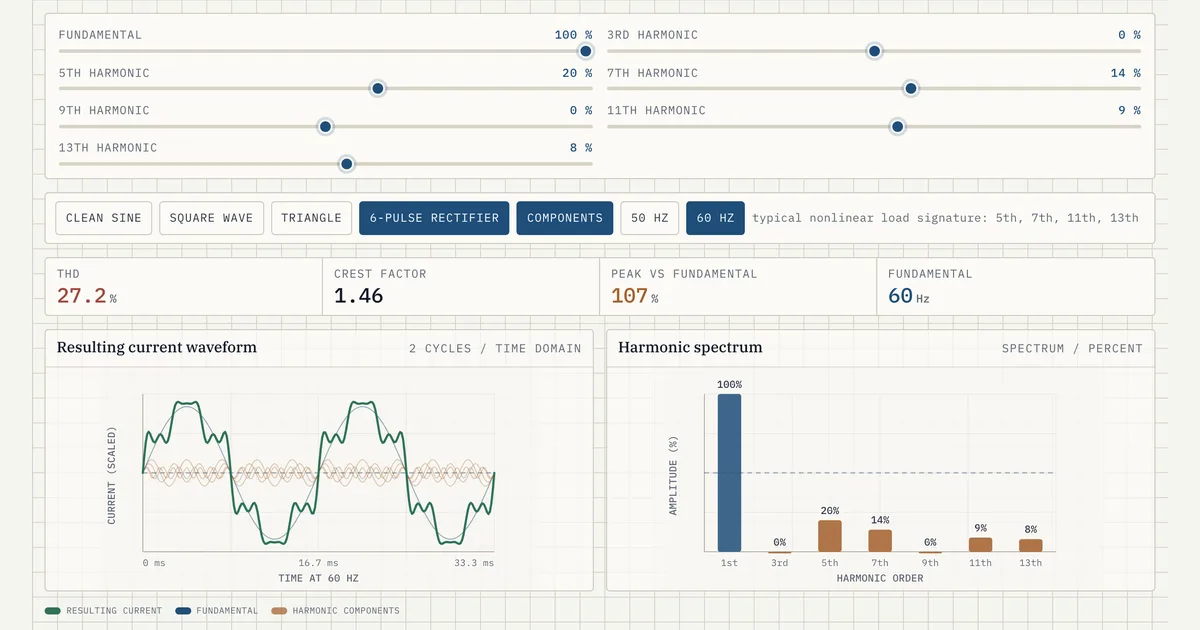
Harmonics are sinusoidal components of AC voltage or current at integer multiples of the fundamental grid frequency (50 or 60 Hz) — the 5th at 250/300 Hz, then the 7th, 11th and 13th. In a grid-scale BESS they come mainly from the power conversion system, whose PWM inverters chop the DC bus at a few kilohertz to synthesize an approximate, not perfect, sine wave.
Aggregate distortion is quantified as total harmonic distortion (THD). You first meet the number on a PCS datasheet, but the one that governs the project is the limit interconnection standards cap at the point of interconnection — around 5% voltage THD at medium voltage under IEEE 519.
New to BESS? Start free in the Learn BESS hub — no cost, no account.
What it is (precise)
Any periodic waveform decomposes into a Fourier series: a fundamental sinusoid plus components at integer multiples. A switched-mode inverter builds its output by chopping the DC bus at high frequency (pulse-width modulation), so the result carries the fundamental plus a spectrum of distortion. Integer multiples are harmonics; non-integer content is interharmonics.
For a utility-scale PCS the residual low-order content sits at the 5th, 7th, 11th and 13th orders, while switching-frequency sidebands cluster around carrier multiples — typically 2-4 kHz — where the LCL output filter attenuates them. Memorize the odd, non-triplen pattern: it is what mitigation targets.
Distortion is measured per-order as individual harmonic distortion and in aggregate as THD, the RMS of all harmonic components over the fundamental. Keep two current metrics apart: THD-I, referenced to the instantaneous fundamental current, and TDD (total demand distortion), referenced to rated or maximum-demand current.
TDD is what IEEE 519 actually limits, because THD-I of a lightly loaded inverter looks alarming even when the harmonic amperes are tiny. Voltage distortion (THD-V) is a separate quantity with its own caps, and the reference point for all three is the point of common coupling, not the inverter terminals.
The current and voltage quantities are linked through the grid: harmonic current the plant injects flows through the network's source impedance and produces harmonic voltage every neighboring customer sees. A stiff grid — high short-circuit ratio — absorbs harmonic current with little voltage distortion; a weak one turns the same amperes into much more THD-V.
Long MV cable runs and shunt capacitor banks add capacitance that can resonate with grid inductance at a low harmonic order, amplifying distortion far beyond what the PCS alone produces. Harmonic performance is a system property, never a single-device number.
Why it matters in a real grid-scale project
Harmonics are a hard interconnection requirement, not a nicety. The utility's system impact study and the interconnection agreement specify allowable distortion at the point of interconnection, and the plant must prove compliance at commissioning with field measurements.
Missing the limit can block energization, force tuned filters onto a fixed site layout, or trigger operating restrictions — schedule and revenue risk that lenders on a financed asset will notice. Retrofitting a filter after energization typically costs an order of magnitude more than designing it in, which is why the harmonic study belongs in the early electrical design, not at commissioning.
Beyond compliance, excess harmonics cause real damage and loss: extra heating in the main transformer and cables (harmonic-rich current forces derating or K-rated designs), nuisance tripping of protection relays, resonance with capacitor banks or long cable runs, and interference with metering, ripple-control and SCADA signals.
Triplen harmonics (3rd, 9th) circulate in delta transformer windings and load the neutral of wye systems. On the BESS side, distorted current shortens filter-capacitor and transformer life and erodes round-trip efficiency through extra copper and iron losses — small percentages that compound over a 20-year life.
 Interactive · bess.engineer ↗
 Key facts
| Fundamental frequency | 50 Hz (IEC grids) / 60 Hz (Americas); 5th = 250/300 Hz, then 7th, 11th, 13th |
|---|---|
| Medium-voltage default to memorize | 1-69 kV band (where most utility BESS connect): 5% voltage THD, 3% single-order |
| IEEE 519 voltage THD limits by tier | 8% (≤1 kV), 5% (1-69 kV), 2.5% (69-161 kV), 1.5% (>161 kV) |
| IEEE 519 individual voltage harmonic limits | 5% / 3% / 1.5% / 1% for the same voltage tiers |
| Binding current metric (not datasheet THD-I) | TDD at the POI; 5% at Isc/IL < 20 stepping to 20% at Isc/IL > 1000 (<69 kV) |
| Low-order residue in PCS current | 5th, 7th, 11th, 13th (odd, non-triplen); triplens 3rd, 9th circulate in delta windings |
| Typical utility-scale PCS switching frequency | ~2-4 kHz; sidebands cluster around carrier multiples, attenuated by the LCL filter |
| Typical full-load PCS current THD | Below ~3% at rated power; rises steeply under ~20-30% load |
| Distribution vs transmission standards | IEEE 1547 / 1547.1 (distribution); IEEE 2800 (transmission IBRs) |
| IEC / European framework | IEC 61000-3-6 / -3-7 emission allocation; EN 50160 voltage quality |
| Compliance measurement methods | IEC 61000-4-7 harmonic analysis, IEC 61000-4-30 Class A instruments |
| Standard mitigation hardware | LCL output filters standard; tuned passive or active filters where the study requires |
Typical values and standards
In North America the governing reference is IEEE 519, which sets limits at the point of common coupling by voltage tier. Voltage THD is capped at 8% up to 1 kV, 5% from 1 kV to 69 kV, 2.5% from 69 kV to 161 kV, and 1.5% above 161 kV, with individual harmonic limits of 5%, 3%, 1.5% and 1% for the same tiers. Most utility-scale BESS connect in the 1-69 kV band, so 5% voltage THD and 3% single-order is the number to carry in your head as the medium-voltage default.
Current limits are expressed as TDD and scale with grid strength: below 69 kV, a weak connection with short-circuit-to-load ratio under 20 gets 5% TDD, loosening in steps to 20% above 1000 — stronger grid, more allowance. Which standard applies depends on where you connect.
Distribution-connected resources fall under IEEE 1547 (1547.1 test procedures), which imports IEEE 519-style limits; transmission-connected inverter-based resources increasingly follow IEEE 2800, which added explicit harmonic current and voltage requirements at the transmission POI. In IEC markets, IEC 61000-3-6/-3-7 allocate each customer a share of network headroom and EN 50160 defines delivered voltage quality.
Modern grid-forming and grid-following PCS units ship well inside these limits at rated load — datasheet current THD is typically below 3% at full power — but distortion is worst at light load, often rising steeply below roughly 20-30% output, and it depends on grid stiffness and background distortion already present.
Where the native output or a weak grid threatens the limit, mitigation is engineered in: LCL output filters (standard on utility-scale PCS), tuned passive filters on the MV bus, active filters, interleaved inverter arrangements, and deliberate transformer vector-group selection to cancel specific orders — all sized from the harmonic study, not bolted on later.
How it shows up in specs, studies and contracts
On a PCS datasheet, find the current THD figure and, critically, its conditions: load level, grid-impedance assumption, and whether it is THD-I or TDD. A bare "THD < 3%" line with no load point is close to meaningless, since the same unit may show 10%+ THD-I at 10% load.
In the interconnection process the term lives in the harmonic (power quality) study, which models the plant's injection spectrum against the utility's frequency-dependent network impedance, including resonance scans across contingencies. Ask the vendor for the harmonic current spectrum per order, not just an aggregate number — the study cannot run without it.
Contractually, harmonics surface in three places. The interconnection agreement fixes the POI limits and the measurement method (usually IEC 61000-4-7 harmonic analysis with IEC 61000-4-30 Class A instruments). The EPC or equipment contract assigns who owns compliance if the commissioning measurement fails.
And the warranty can be voided by operation outside distortion limits — a transformer or filter clause worth reading. Two questions worth asking on every project: how is pre-existing background distortion allocated between plant and network, and does the P-Q capability commitment still hold with the filters in service, since tuned filters add capacitive reactive power that shifts the operating envelope.
Common pitfalls
The classic trap is comparing a datasheet THD-I number against an IEEE 519 TDD limit — different denominators, different quantities. A second is measuring compliance at the inverter terminals instead of the point of common coupling, or during one full-load test window that misses the light-load and standby conditions where percentage distortion peaks.
A third is ignoring background harmonics: on a distorted network the plant absorbs harmonic current from the grid, and a naive measurement blames the BESS. Directional harmonic analysis plus a pre-energization baseline survey keep the project from paying for the network's pre-existing pollution.
Resonance is the pitfall that surprises otherwise clean designs. Kilometers of MV collector cable, the LCL filters, power-factor-correction capacitors and transformer inductance form a resonant circuit whose amplification peak can land on a low characteristic order — and the peak moves as the utility reconfigures the network or as containers switch in and out.
Design margin means checking the resonance scan across grid contingencies and plant states, not one snapshot. Finally, ride-through events and unbalanced conditions temporarily raise distortion; standards assess harmonics under normal operation, so conflating fault-window waveforms with steady-state compliance creates false alarms.
Common misconception
If the PCS datasheet lists a low THD, the plant automatically passes the grid's harmonic limit.
In reality: The binding limit is TDD at the point of interconnection for the whole installation, and the datasheet figure is usually THD-I — a different quantity with a different denominator, measured at the inverter terminals under ideal lab load. Real distortion depends on load level (percentage THD is worst at light load), grid short-circuit strength (a weak grid turns the same harmonic current into more voltage distortion), background harmonics already on the network, and possible resonance between site cabling, filters and capacitor banks. Only a design-stage harmonic study and commissioning field measurements prove compliance.
Visuals & further reading
- Interactive: Current Harmonics and THD Interactive visual · bess.engineer
- Interactive: PWM: Building a Sine from a DC Bus Interactive visual · bess.engineer
Harmonics, in context.
The Grid-Scale BESS course covers harmonics — and the rest of the system — from the ground up, the way it actually gets deployed.