Cell
Battery Essential term
Reviewed October 2026 by Sergey Syrvachev
A cell is the smallest electrochemical unit in a battery energy storage system — a single sealed package of electrodes, separator, and electrolyte that stores and releases energy at a low DC voltage, typically around 3.2 V nominal for LFP. In grid-scale stationary storage, cells are series- and parallel-connected into modules, modules stack into racks, and racks fill a container.
A modern large-format LFP cell of roughly 314 Ah stores about 1 kWh, so a single 5 MWh container holds on the order of 5,000 cells, and every megawatt-hour delivered at the point of interconnection originates from thousands of them operating together.
Back to the free route: The system — no cost, no account.
What it is (precise)
A cell is the indivisible building block of the storage system: an anode and a cathode separated by an ion-permeable separator, wetted by electrolyte, with metal current collectors carrying electrons out through the terminals, all sealed in a prismatic, pouch, or cylindrical case.
It is the only place where energy is actually stored electrochemically — everything above it in the hierarchy (module, rack, container, power conversion system) is packaging, wiring, cooling, control, and conversion. Utility-scale BESS overwhelmingly uses large prismatic cells with aluminum cases; pouch and cylindrical formats are more common outside stationary storage.
The cell fixes the system's fundamental traits: nominal voltage, energy density, round-trip efficiency, degradation behavior, and thermal-runaway characteristics. The dominant stationary chemistry today is lithium iron phosphate, chosen for its higher thermal-runaway onset temperature, absence of an oxygen-releasing cathode, long cycle life, and lower cost per cycle.
NMC appears mainly as a higher-energy-density contrast where footprint is severely constrained, and sodium-ion is emerging as a lithium-free alternative. Cell voltage also sets the system architecture: with LFP at ~3.2 V nominal, a 1500 VDC bus limits a series string to roughly 416 cells, which is why rack voltages cluster where they do.
Why it matters in a real grid-scale project
Cell choice cascades into nearly every project metric. Cell capacity and count drive how many racks and containers are needed to hit a contracted MWh, which in turn drives land area, foundations, cabling, and balance-of-plant cost. The move from 280 Ah to 314 Ah and now 500–600+ Ah formats exists precisely to cut parts count and container count per MWh: fewer cells means fewer welds, fewer busbar joints, fewer sensing channels, and fewer failure points per megawatt-hour installed.
Cell degradation sets the augmentation schedule — the additional capacity installed over a 15-to-20-year term to keep meeting guaranteed energy — a major line item in any project finance model.
Cells also define the safety envelope: because thermal runaway initiates at the cell, cell abuse behavior governs container spacing, deflagration venting, and the explosion-mitigation measures an authority having jurisdiction will require. A cell datasheet and its test data are therefore not just an electrical spec — they are an input to siting, permitting, insurance, and the bankability of the entire asset.
Key facts
| Dominant stationary chemistry | LFP (LiFePO4); NMC as higher-density contrast; sodium-ion emerging |
|---|---|
| Nominal cell voltage | ~3.2 V LFP (window ~2.5–3.65 V); ~3.6–3.7 V NMC |
| Mainstream large-format capacity | 280–320 Ah today; 500–600+ Ah formats emerging (~1 kWh per 314 Ah LFP cell) |
| Energy density (cell level) | LFP ~160–190 Wh/kg; NMC ~200–280 Wh/kg |
| Cell round-trip efficiency (DC-DC) | Typically 95–98% at 0.25C–0.5C stationary duty |
| Cycle life (LFP) | Several thousand warranted; 6,000–10,000+ cycles claimed to 70–80% of BOL under rated conditions |
| Series count at 1500 VDC | Up to ~416 LFP cells in series per string |
| Cells per 5 MWh container | On the order of 5,000 (314 Ah class) |
| Preferred operating temperature | Roughly 15–35 °C; excursions accelerate degradation |
| Cell/battery safety standards | UL 1973 (stationary battery, cell to rack); IEC 62619 (industrial lithium cells and batteries); UN 38.3 (transport) |
| Fire/propagation test method | UL 9540A (cell → module → unit → installation scale-up); data feeds NFPA 855 |
| Installation & explosion protection | NFPA 855; NFPA 68 (deflagration venting) / NFPA 69 (prevention) |
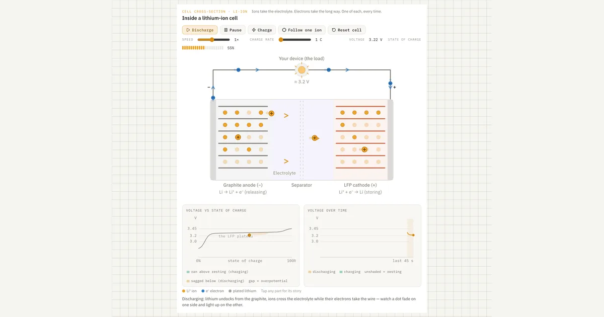 Interactive · bess.engineer ↗
 Typical values and standards
Anchor numbers for stationary LFP: ~3.2 V nominal with an operating window of roughly 2.5–3.65 V per cell; NMC sits near 3.6–3.7 V nominal. Large-format stationary cells run 280–320 Ah as the current mainstream, with 500–600+ Ah formats entering the market — at ~314 Ah and 3.2 V, one cell is about 1 kWh. Gravimetric energy density for large prismatic LFP is typically 160–190 Wh/kg (NMC roughly 200–280 Wh/kg), and cell-level DC-DC round-trip efficiency is typically 95–98% at the gentle 0.25C–0.5C rates a 2-to-4-hour system actually runs.
Cycle life is quoted to a defined end-of-life, commonly ~65-70% of beginning-of-life capacity: LFP vendors typically warrant several thousand full cycles, with headline claims of 6,000–10,000+ cycles under specific temperature, C-rate, and depth of discharge conditions.
Calendar aging runs in parallel with cycle aging, so a lightly cycled cell still degrades — both mechanisms feed the state of health trajectory that warranties and augmentation plans are built on. Optimal cell temperature is roughly 15–35 °C; sustained operation hot or cold accelerates fade, which is why liquid cooling now dominates new utility-scale designs.
On standards: UL 1973 evaluates the stationary battery from cell through pack and rack, and IEC 62619 covers safety of secondary lithium cells and batteries for industrial applications — these are the cell and battery-level safety evaluations. UL 9540A is the test method that characterizes fire and thermal-runaway propagation, deliberately scaling from cell to module to unit and, where needed, installation level; its data feeds NFPA 855, the installation standard.
NFPA 68 and NFPA 69 cover deflagration venting and explosion prevention respectively, and UN 38.3 governs transport of the cells to site. UL 9540 is the separate system-level ESS safety certification — never conflate it with the 9540A test method.
How it shows up in specs, studies and contracts
On a cell datasheet, check nominal capacity and the conditions it is rated at (temperature, C-rate, voltage window), internal resistance, mass and dimensions, cycle life curves with their test conditions, and the abuse test results. Ask which capacity the integrator's MWh math uses — cell nameplate at beginning-of-life is not the deliverable energy at the point of interconnection, which is further reduced by the state of charge window the BMS enforces, DC and conversion losses, and degradation to end-of-life. Contracted energy guarantees should state their reference point and year explicitly.
In supply contracts and warranties, the cell appears through capacity-retention guarantees tied to an operating envelope: cycles per year, average state of charge, resting SOC, C-rate, and temperature limits. Exceed the envelope and the warranty thins or voids, so the dispatch profile assumed in the revenue model must be checked against the warranty terms — a cycle definition (full equivalent cycles vs. counted events) is itself a negotiated term. Augmentation pricing, cell traceability (serial-level records), and end-of-life criteria all trace back to cell-level data.
In permitting and interconnection work, the cell surfaces through the UL 9540A test report package the fire marshal reviews, through the hazard mitigation analysis under NFPA 855, and through the heat output and gas volumes that size deflagration vents. In due diligence, independent engineers increasingly ask for cell-level factory audit reports and statistical capacity distribution of delivered cells, since cell-to-cell spread at delivery predicts balancing burden and early-life divergence in the field.
Common pitfalls
The most common unit trap is treating cell amp-hours as if they translated straight to system megawatt-hours. Between cell and POI sit series-parallel derates, the usable SOC window, cell-to-cell mismatch, DC cabling and busbar losses, PCS and transformer efficiency, and auxiliary loads — a system quoted at nameplate DC MWh can deliver meaningfully less AC energy, and the gap grows toward end-of-life. Always ask for the energy statement basis: BOL or EOL, DC or AC, nameplate or usable.
A second trap is reading cycle life as a single number. The 8,000-cycle headline was measured at one temperature, one C-rate, one depth of discharge, and usually 100% DoD equivalence accounting; your project's mixed duty cycle, resting SOC, and site ambient produce a different trajectory. Degradation is also nonlinear — many chemistries show a knee late in life — so extrapolating the first two years of state of health data linearly to year 20 systematically flatters the augmentation budget.
Common misconception
A bigger cell with more amp-hours always means a better, higher-performing battery system.
In reality: Higher cell capacity reduces parts count, but usable system energy is governed by cell-to-cell uniformity, degradation rate, thermal management, and BMS balancing. A pack of well-matched, thermally stable cells often delivers more bankable lifetime energy than one built around higher-capacity but less consistent cells, and a larger cell concentrates more energy and vented gas per thermal-runaway event — a design consideration that shows up directly in UL 9540A results and NFPA 855 hazard mitigation analysis.
Visuals & further reading
- Interactive: Lithium-Ion Cell Interactive visual · bess.engineer
- Interactive: Cell Losses & Efficiency Interactive visual · bess.engineer
- Sodium-Ion vs LFP for Grid Storage — and Where NMC Still Fits Article
Cell, in context.
The Grid-Scale BESS course covers cell — and the rest of the system — from the ground up, the way it actually gets deployed.