Anode
Battery Essential term
Reviewed October 2026 by Sergey Syrvachev
In a lithium-ion cell the anode is the negative electrode — the host that lithium ions move into during charging. In grid-scale stationary storage it is almost always graphite (theoretical capacity 372 mAh/g as LiC6) coated onto copper foil typically 6-10 µm thick, occasionally blended with a few percent silicon to raise capacity.
On charge, ions leave the cathode, cross the separator, and intercalate between the graphite layers; on discharge they return while electrons do work through the external circuit. Because most calendar and cycle aging happens at this electrode, the anode quietly sets the charge limits, the cycle-life warranty, and much of the safety case for the whole system.
New to BESS? Start free in the Learn BESS hub — no cost, no account.
What it is (precise)
The anode is the lithium-host electrode: graphite particles bound with polymer and coated onto a copper current collector that carries electrons to the cell tabs. Each graphite layer stores lithium between its planes, reaching LiC6 at 372 mAh/g, which with the cathode fixes usable cell capacity. Graphite sits at roughly 0.05-0.2 V versus lithium metal — an unusually low potential that gives lithium-ion its high cell voltage but leaves only a thin margin against plating metallic lithium.
In stationary BESS the dominant pairing is graphite with lithium iron phosphate; NMC cells reuse the same graphite anode behind a more energetic cathode. Formally "anode" names whichever electrode oxidizes, so the label swaps between charge and discharge — the industry just fixes it to graphite by convention.
Designers deliberately oversize the anode relative to the cathode — the N/P ratio, typically around 1.05-1.15 — so the graphite never runs out of vacant sites before the cathode empties, the first line of defense against plating.
Some cells blend a few percent of silicon oxide into the graphite; silicon stores roughly ten times more lithium per gram but swells about 300 percent when lithiated, so long-life stationary cells use it sparingly or avoid it. Over the first few charges the anode grows the solid-electrolyte interphase, a passivation film that permanently consumes roughly 5-10 percent of the cell's lithium and then governs much of its aging for the next two decades.
Why it matters in a real grid-scale project
For a utility-scale owner the anode is where most calendar and cycle degradation lives, and degradation is a financial line item. The solid-electrolyte interphase keeps thickening over years — faster at high state of charge and high temperature — while lithium plating, metallic lithium depositing on the graphite instead of intercalating, is the failure mode that erodes capacity and can seed internal shorts.
Both are driven by charging too hard, too cold, or too full. That is why the BMS enforces charge-rate and temperature limits, why containers carry HVAC or liquid cooling, and why augmentation is written into the energy guarantee from day one rather than bolted on later.
Anode-side plating also sits behind the thermal-runaway scenarios that drive site safety design. A plated, aged, or mechanically damaged anode can short through the separator and trigger runaway in one cell — exactly the event that NFPA 855 spacing, deflagration venting, and gas detection are sized to contain.
Charge-acceptance limits even shape operations: a stationary system cycling at 0.25C-0.5C stresses its graphite far less than an EV fast-charging at 2-3C, which is one structural reason grid batteries can credibly target 6,000-10,000 cycles while automotive packs cannot. When you compare a stationary and an automotive datasheet side by side, this is the physics underneath the difference.
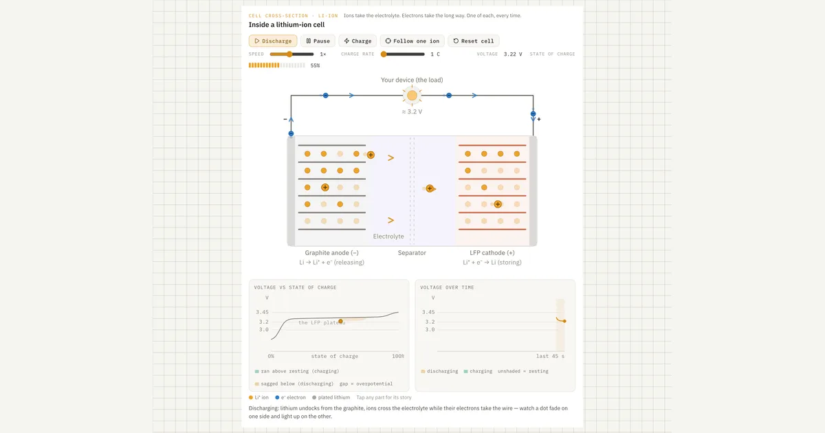 Interactive · bess.engineer ↗
 Key facts
| Graphite capacity | 372 mAh/g theoretical (LiC6); 340-360 mAh/g in practice |
|---|---|
| Anode potential | ~0.05-0.2 V vs Li/Li+ (thin margin against lithium plating) |
| Current collector | Copper foil, typically 6-10 µm |
| N/P ratio | Typically ~1.05-1.15 (anode oversized to block plating) |
| First-cycle SEI loss | Typically 5-10% of lithium, irreversible |
| Silicon blending | ~10x lithium per gram but ~300% swelling — used sparingly in stationary cells |
| Charge vs discharge window | Discharge often to ~-20 °C, but charge only ~0 °C to 45-55 °C (upper limit cell/BMS-dependent, commonly ~45 °C); sub-0 °C charging plates lithium |
| Typical stationary charge rate | 0.25C-0.5C (vs 2-3C EV fast charge) |
| Cycle-life context | 6,000-10,000+ cycles quoted for LFP-graphite cells (at reference conditions) |
| End-of-warranty energy | Typically ~65-70% of beginning-of-life; augmentation fills the gap |
| Alternative anodes | LTO (1.55 V, 15,000+ cycles, niche); hard carbon (~300 mAh/g, sodium-ion) |
| Standards chain | UL 1973 / IEC 62619 (cells, batteries, racks), UL 9540 (system cert), UL 9540A (propagation test), NFPA 855, NFPA 68/69 |
Typical values and standards
Numbers worth carrying in your head: graphite delivers 340-360 mAh/g in practice against the 372 mAh/g ceiling; copper foil runs 6-10 µm; first-cycle irreversible loss is typically 5-10 percent; and charging below about 0 °C without derating invites plating, so BMS charge windows commonly span roughly 0 °C to 45-55 °C with taper at the edges — the upper charge limit is cell/BMS-dependent, commonly ~45 °C, above which charge current must be derated.
Alternative anodes live at the market's margins: lithium titanate (LTO) sits at 1.55 V versus lithium, forms essentially no SEI, and cycles 15,000-plus times, but low energy density and cost confine it to niche duty. Sodium-ion cells swap graphite for hard carbon at roughly 300 mAh/g and can use cheaper aluminum current collectors on both electrodes.
The anode never carries its own certificate — it is qualified through the cell and system chain. UL 1973 covers batteries for stationary use at cell, module, and rack level; IEC 62619 is the international counterpart for industrial lithium cells; UL 9540 certifies the complete energy storage system; and UL 9540A is the test method that characterizes thermal-runaway propagation and vent-gas composition — that flammable gas mix originating largely from electrolyte decomposition at the hot anode surface.
NFPA 855 governs installation, with NFPA 68/69 covering deflagration venting and prevention. Treat any per-cell figure as vendor-specific and confirm it against the actual datasheet and UL 9540A report before it enters a model.
How it shows up in specs, studies and contracts
On a cell datasheet the anode appears as one line — "graphite," "artificial graphite," occasionally "graphite + SiOx" — but its fingerprints are everywhere: the charge temperature window, the maximum continuous and peak charge C-rate, the cycle-life number and the exact conditions behind it (typically 25 °C, 0.5C/0.5C, 100 percent depth of discharge or a stated window), and the calendar-fade curve.
The binding constraint is rarely the headline cycle count; it is the conditions attached to it. Ask the vendor point-blank whether cycle-life was measured at the charge rate and temperature your dispatch profile implies — a 10,000-cycle rating proven at 25 °C says little about a site charging hard on winter mornings.
In warranty and capacity-maintenance agreements the anode's failure modes become contract language. BMS-logged charge-window violations are standard warranty exclusions; the guaranteed state of health fade curve assumes the vendor's reference duty profile; and end-of-warranty energy is usually pegged around 65-70 percent of beginning-of-life, with augmentation filling the gap.
In safety submittals the unit-level UL 9540A report is where anode-driven runaway becomes hard data — gas volumes, lower flammability limits, heat release — that the fire-protection engineer and the AHJ actually read. Two questions earn their keep: does the warranty profile match your real duty cycle, and if silicon content is nonzero, how was swelling handled in module design and what does it do to the fade curve?
Common pitfalls
Three recurring traps. First, transplanting EV intuition: automotive cells chase fast charge and energy density with silicon-rich anodes, while stationary cells trade both for cycle life — comparing their specs head-to-head misleads procurement.
Second, ignoring the plating corner: the dangerous region is low temperature, high charge rate, and high state of charge occurring together, and a dispatch profile that looks benign on average can still visit that corner every winter morning. Third, assuming the anode ports across chemistries: hard carbon in sodium-ion cells has a different voltage profile and SOC-estimation behavior than graphite, so BMS state estimation and augmentation planning do not carry over unchanged.
Common misconception
A cell's rated temperature range applies equally to charging and discharging.
In reality: Charging is the narrower, more fragile window. Many LFP cells discharge down to about -20 °C but must not be charged below roughly 0 °C without derating, because at low temperature lithium plates onto the graphite anode instead of intercalating — permanent capacity loss and a potential internal-short seed. Treat the charge temperature window, not the wider discharge range, as the binding limit, and confirm the BMS actually enforces it before energy ever reaches the cells.
Visuals & further reading
- Interactive: Lithium-Ion Cell Interactive visual · bess.engineer
- Sodium-Ion vs LFP for Grid Storage — and Where NMC Fits Article
- Sodium Batteries, Part 1: How the Technology Actually Works Article
Anode, in context.
The Grid-Scale BESS course covers anode — and the rest of the system — from the ground up, the way it actually gets deployed.