Separator
Reviewed October 2026 by Sergey Syrvachev
In a lithium-ion cell, the separator is a thin microporous membrane, typically 10 to 25 micrometers thick, that sits between the anode and the cathode and keeps them from touching while letting the electrolyte and lithium ions pass.
Picture the cell as anode, separator, cathode, and two current-collector foils wound or stacked together: the separator is the referee that permits ions but blocks electrons. In a grid-scale BESS it is the smallest part most engineers never see, yet it sets a cell's internal safety margin, impedance, and abuse behavior, and sits behind every UL 9540A propagation number a project is permitted on.
New to BESS? Start free in the Learn BESS hub — no cost, no account.
What it is (precise)
The separator is an electrically insulating but ionically conductive film, usually about 10 to 25 micrometers thick, made of a microporous polyolefin (PE, PP, or a PE/PP/PE trilayer), increasingly a ceramic-coated variant.
Its pore network floods with liquid electrolyte so lithium ions can migrate between the anode and cathode, while its solid polymer matrix blocks electron flow and prevents direct electrode contact. It is wound or stacked with the electrode foils and their current collector layers inside every prismatic or cylindrical cell that makes up a grid-scale rack, with sub-micron pores and about 40 to 50 percent porosity.
Manufacturing route matters. Dry-process separators (uniaxially stretched PP or trilayers) have slit-like pores and are the classic safety-oriented choice; wet-process PE separators have more tortuous, uniform pores and dominate high-volume production.
In the dominant stationary chemistry, lithium iron phosphate, separators are typically wet-process polyolefin with a thin ceramic coating, usually alumina or boehmite, roughly 1 to 5 microns per side, for thermal stability. Higher-energy NMC cells lean harder on ceramic-coated and reinforced separators because their cathodes release oxygen at lower temperatures during a thermal event.
Electrically, the separator is a series resistance in the ion path. Its contribution is captured by the MacMullin number, the ratio of electrolyte-filled separator resistance to an equivalent slab of free electrolyte, typically around 5 to 15 for commercial films, and by air permeability quoted as a Gurley value, commonly 100 to 300 seconds per 100 cc.
A thicker, more tortuous separator raises impedance and heat at high C-rate; a thinner one gives up puncture margin. Stationary cells, cycling gently at 0.25C to 0.5C (a 4-hour to 2-hour duration), can afford thicker, safety-biased separators than energy-dense EV cells run at 1C or more.
Why it matters in a real grid-scale project
The separator is the first line of defense against internal short circuits, the failure mode that initiates thermal runaway. A pinhole, a metallic contaminant particle, a lithium dendrite grown by low-temperature or overcurrent charging, or a mechanical crush that breaches the separator creates a localized hot spot that can propagate cell to cell across a module, then a rack, then a container.
At grid scale, with megawatt-hours in one enclosure, this is the difference between a contained nuisance and a multi-rack fire that drives NFPA 855 separation distances, deflagration venting, and insurance and interconnection review.
Separator quality therefore feeds directly into the cell-level test data that underpins a project's UL 9540A results, the propagation behavior the authority having jurisdiction (AHJ) and fire marshal will scrutinize, and ultimately the bankability of the asset.
It is not a line item the EPC specifies, but it is embedded in the cell datasheet and the manufacturer's abuse-test pedigree that owners and lenders rely on during technical due diligence. Field-failure statistics reinforce the point: a large share of documented BESS cell failures trace back to internal shorts seeded by manufacturing defects, which separator integrity exists to survive.
The separator also shapes long-term performance. Pore clogging by decomposition products, compression under stack pressure, and dendrite penetration raise cell impedance over life, one of the mechanisms behind state of health decline alongside lithium-inventory loss at the solid-electrolyte interphase. A separator that keeps its porosity over 6,000-plus full cycle counts is part of why an LFP cell can credibly warrant 65 to 70 percent capacity retention after 20 years of daily cycling.
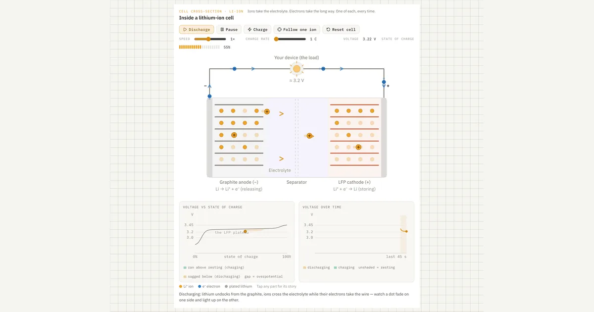 Interactive · bess.engineer ↗
 Key facts
| Typical thickness | ~10-25 microns; stationary cells sit at the thicker, safety-biased end |
|---|---|
| Typical porosity | ~40-50%; pore size tens of nanometers to sub-micron |
| Common material | Microporous polyolefin (PE, PP, or PE/PP/PE trilayer), often with a ~1-5 micron alumina/boehmite ceramic coat per side |
| Shutdown temperature (PE) | ~130-135 degrees C (pores close, choking ion flow); PP layer holds to ~160-165 degrees C |
| Ceramic-coat benefit | Dimensional integrity well above ~180 degrees C; some films <5% shrinkage at 200 degrees C |
| Air permeability (Gurley) | Typically ~100-300 s/100 cc (higher = more tortuous, higher impedance) |
| MacMullin number | ~5-15 for commercial films (separator resistance vs free electrolyte) |
| Thermal shrinkage spec | Usually <~5% after 1 h at 90-120 degrees C |
| Share of cell cost | Typically single-digit %, so a ceramic upgrade is one of the cheapest safety levers |
| Default stationary chemistry | LFP (NMC is the higher-energy, more abuse-sensitive contrast); sodium-ion reuses the same films |
| Relevant standards | UL 9540A (propagation test method), UL 9540 (ESS cert), UL 1973, IEC 62619, NFPA 855, NFPA 68/69 |
| Failure modes it guards against | Internal shorts from contaminant particles, lithium-plating dendrites, mechanical crush, each a thermal-runaway trigger |
Typical values and standards
Two temperatures dominate the separator's safety story. The first is the shutdown temperature, where polyethylene melts and its pores close to choke ionic flow, commonly around 130 to 135 degrees C for PE; a PP layer in a trilayer melts higher, near 160 to 165 degrees C, holding the film together after PE shutdown. The second is the meltdown or integrity temperature, above which an uncoated separator loses mechanical strength and shrinks, defeating its own shutdown. Ceramic coatings hold dimensional integrity well above 180 degrees C, and some show under 5 percent shrinkage at 200 degrees C.
Mechanical and quality metrics matter too: puncture strength (typically a few hundred grams-force for a 20-micron film), tensile strength, and thermal shrinkage, usually specified below roughly 5 percent after an hour at 90 to 120 degrees C. Separator material is typically a single-digit percent of cell cost, so a ceramic-coat upgrade is a cheap safety lever. Sodium-ion cells use essentially the same polyolefin separators, so the component carries over as that chemistry enters stationary service.
Engineers do not test separators directly; they read their performance through cell- and unit-level testing.
The framework is UL 9540A, the test method characterizing thermal-runaway fire propagation, whose data feeds NFPA 855 installation requirements; UL 1973, the safety certification for stationary battery packs and racks, and IEC 62619, its international counterpart, both of which include internal-short and abuse tests that exercise the separator; UL 9540, the system-level ESS safety certification (distinct from the 9540A test it cites); and NFPA 68 and 69 for deflagration venting and prevention at the enclosure level.
How it shows up in specs, studies and contracts
A working engineer rarely sees a separator datasheet. On the cell specification it is often a single line, "ceramic-coated separator," with no thickness or temperatures given. It also surfaces in the UL 9540A cell-level test report, where thermal-runaway onset temperature and vent-gas composition are indirect evidence of separator behavior, and in failure-analysis reports and supplier due-diligence questionnaires.
During vendor evaluation, ask four concrete things: is the coating on one side or both; what are the shutdown and meltdown temperatures in degrees C; what metallic-contaminant limit (parts per billion) governs electrode production; and how do those numbers translate into the module-level propagation result the AHJ will require.
Contracts encode separator physics without naming it, and this is where projects get burned. Warranty clauses that prohibit charging below 0 degrees C or above a stated C-rate exist largely to prevent lithium plating and the dendrites that puncture separators; a single mis-set EMS or BMS limit can void a 20-year warranty.
Cycle-life warranties assume the separator's impedance and porosity hold as specified. And if a cell supplier changes separator vendor or coating mid-production, that is a form-fit-function change worth a change-notification clause, because it can invalidate the UL 9540A data your fire-permit package was built on.
Common pitfalls
The biggest trap is treating shutdown as a guarantee. Shutdown is a one-shot, passive mechanism that only works if the cell heats slowly and uniformly enough for the whole film to close before any point reaches meltdown. In a hard internal short, local temperature can blow past 500 degrees C in seconds, far beyond any polymer's limit, and in a large-format prismatic cell a shutdown that closes pores in one region simply forces current through the rest. Ceramic coatings and cathode chemistry (LFP versus NMC) do far more for real propagation resistance than the shutdown feature on its own.
A second trap is assuming separator specs are static. Films thin over life under stack pressure, oxidize at high voltage, and can be locally compromised by a single sub-zero fast-charge excursion with no immediate symptom; the resulting dendrite may take months of cycling to complete a short. That is why BMS temperature and charge-rate limits are safety controls, not performance suggestions, and why self-discharge and cell voltage-spread monitoring across a rack is the fleet operator's practical early-warning signal for a developing separator breach.
Common misconception
A shutdown separator makes the cell intrinsically safe: once it hits ~130 degrees C the pores close and thermal runaway is stopped.
In reality: Shutdown is a one-shot mechanism that only helps in slow, uniform heating. A hard internal short drives local temperature past the polymer's meltdown limit in seconds, and in large-format cells a partial shutdown just concentrates current elsewhere. Real propagation resistance comes from ceramic coatings, cathode chemistry (LFP vs NMC), and cell design together, which is exactly what UL 9540A cell and module tests measure and what the AHJ reviews before permitting the site.
Visuals & further reading
- Interactive: Lithium-Ion Cell Interactive visual · bess.engineer
- BESS Fire Safety in 2026: Thermal Runaway, NFPA 855, and What the Incidents Taught Us Article
- Sodium-Ion vs LFP for Grid Storage — and Where NMC Still Fits Article
Separator, in context.
The Grid-Scale BESS course covers separator — and the rest of the system — from the ground up, the way it actually gets deployed.