BESS
BESS system Essential term
Reviewed October 2026 by Sergey Syrvachev
BESS stands for Battery Energy Storage System: the complete grid-connected installation that stores electrical energy in batteries and returns it on command.
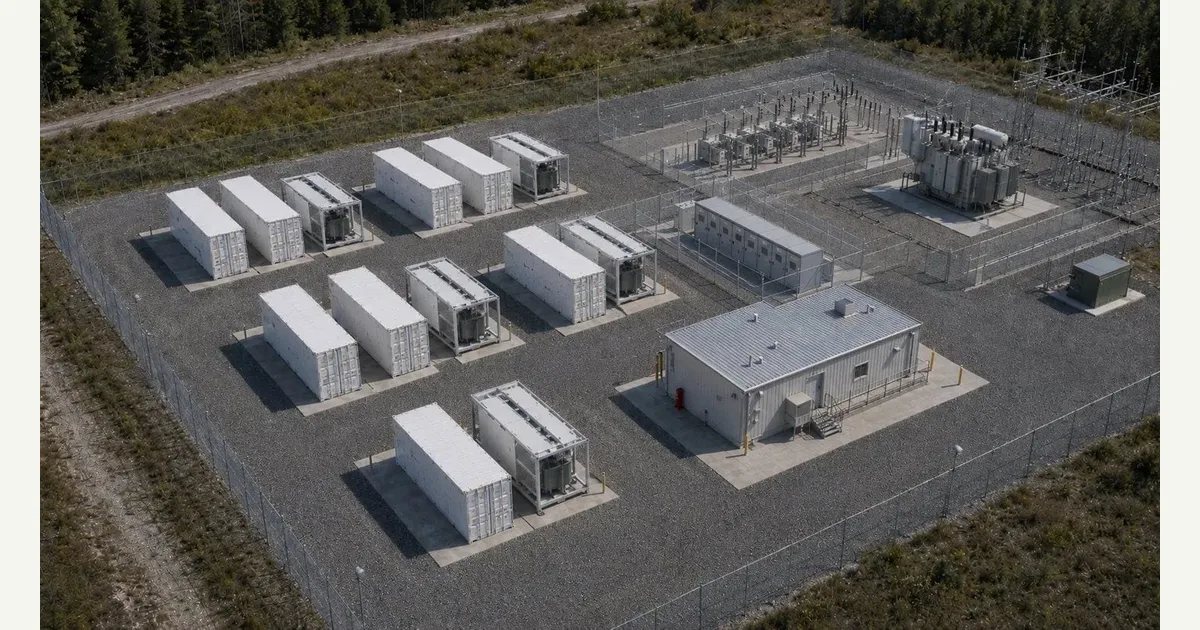
It is not the battery cells alone but the whole engineered system — cells assembled into modules, racks and containers, the power conversion system (PCS) that inverts DC to AC, medium-voltage transformers, switchgear and protection, plus the controls, thermal management and fire-safety systems that make it dispatchable at the point of interconnection (POI).
A utility-scale BESS is specified by two independent numbers: power in MW and energy in MWh, whose ratio sets duration in hours — a 100 MW / 400 MWh plant is a 4-hour system running at 0.25C.
Back to the free route: Fundamentals — no cost, no account.
What a BESS actually is (precise)
At utility scale a BESS is a layered system, not a product. The hierarchy runs cell, module, rack, container, block, plant. Large-format prismatic LFP cells — commonly in the 280 to 320 Ah class today, with larger formats emerging — are series/parallel-assembled into modules, then racks, each supervised by its own battery management system (BMS) layer.
Racks are wired in series onto a DC bus that in current designs sits at or below 1500 VDC, and the acceptable VDC window of the connected PCS sets how many cells can be strung together and how deeply they can be discharged before the string leaves that window.
Racks live inside a container / enclosure — walk-in or, increasingly, non-walk-in cabinet-style units — that also carries HVAC or liquid cooling, gas detection and deflagration venting. Each DC block feeds a PCS, typically a 1 to 5 MVA block sized in MVA rather than MW because it must supply reactive power too, that converts DC to grid-synchronous AC.
PCS output is stepped up by a medium-voltage transformer, collected through MV switchgear, and delivered to the POI. Above the hardware sits a controls stack — BMS, PCS controller, site EMS and plant controller — that enforces dispatch setpoints, state-of-charge limits and grid-code response. The cells store energy; the rest of the system is what makes it a grid asset.
Why the full-system view matters on a real project
Treating a BESS as "the batteries" is where projects go wrong. Round-trip efficiency, deliverable power and warranty all depend on the chain outside the cells: PCS efficiency and temperature derating, the auxiliary load that HVAC and controls draw around the clock, transformer and collection losses, and POI voltage and frequency constraints.
AC capacity measured at the POI is always less than the nameplate DC energy implies — often 10 to 20 percent lower once every loss and the usable SOC window are counted — and it is the POI number that drives revenue, capacity-market obligations and liquidated damages, not the sticker on the container.
The system framing also governs cost, schedule and risk. Fire and life-safety engineering — clearances, deflagration panels, suppression, emergency response plans — can dominate site layout and permitting.
Augmentation, adding racks or containers over the 15-to-20-year project life to offset cell degradation, must be designed in from day one: spare pad space, PCS or DC-bus headroom, and a BMS/EMS architecture that tolerates mixed-age blocks. Interconnection studies, grid-code compliance and EMS integration frequently sit on the critical path far longer than cell procurement does, so schedule risk lives in the balance-of-system, not the cells.
 Interactive · bess.engineer ↗
 Key facts
| Defining ratings | Power (MW) and energy (MWh) are independent; duration [h] = MWh / MW |
|---|---|
| Rate of use (C-rate) | C-rate = power / energy; 4 h = 0.25C, 2 h = 0.5C |
| Round-trip efficiency (AC-AC, POI) | Typically mid-80s to low-90s %; RTE ~ (one-way)², so ~95% one-way ~ ~90% RTE; DC-DC cell figure is higher |
| Binding contract number | Deliverable energy at the POI at EOL, not DC nameplate at BOL |
| Dominant chemistry | LFP (higher TR onset, no O2-releasing cathode); NMC is the higher-density contrast case |
| DC bus voltage | Up to 1500 VDC typical; 2000 V architectures emerging |
| PCS block size | ~1-5 MVA per block; sized in MVA not MW because S² = P² + Q² |
| Container to plant scale | ~5 MWh per 20-ft-class enclosure (older air-cooled 1-3.5 MWh; high-density 5-6+ MWh), so 100 MW / 400 MWh ~ 70-80 containers |
| Auxiliary load | ~1-3% of annual throughput, drawn 24/7 by HVAC and controls, climate-dependent |
| Availability guarantee | Typically ~95-98% (up to ~99%) in supply/O&M contracts |
| Safety certification vs fire test | UL 9540 (system certification) is NOT UL 9540A (thermal-runaway test feeding NFPA 855); UL 1973 cell-to-rack, IEC 62619 international counterpart, NFPA 68/69 venting |
| Grid interconnection | IEEE 1547 (distribution) / IEEE 2800 (transmission IBR) / TO-specific codes; modeled as an inverter-based resource |
Typical values and standards worth memorizing
Stationary BESS today is dominated by LFP for its higher thermal-runaway onset temperature, absence of an oxygen-releasing cathode, long cycle life and lower cost; NMC offers higher energy density but is now the contrast case, largely confined to space-constrained sites.
A current 20-foot-class enclosure typically packages roughly 5 MWh (older air-cooled units 1-3.5 MWh; high-density designs 5-6+ MWh), so a 100 MW / 400 MWh site is on the order of 70 to 80 containers plus power conversion and collection. DC buses run at up to 1500 VDC, with 2000 V architectures emerging to cut balance-of-system cost, and durations cluster at 2 to 4 hours (0.25 to 0.5C), trending longer as energy shifting displaces pure capacity plays.
AC-to-AC round-trip efficiency measured at the POI typically lands in the mid-80s to low-90s percent once PCS, transformer and auxiliary losses are counted; because RTE is roughly the one-way efficiency squared, a 95 percent one-way path yields about 90 percent round trip.
The DC-DC cell-level figure is several points higher, which is why the measurement basis must always be stated. Auxiliary load is commonly 1 to 3 percent of annual throughput, climate-dependent, and availability guarantees typically sit around 95 to 98 percent (up to about 99 percent). Remember RTE is not SOC and SOC is not SOH — three different numbers that all read as percentages.
The governing references in North America split cleanly by role, and mixing them up is a classic exam trap. UL 9540 is the product/system safety certification for the ESS as a whole; UL 9540A is a thermal-runaway fire-propagation test method whose data feeds NFPA 855, the installation standard, in justifying spacing and protection — the certification and the test are not interchangeable.
UL 1973 covers the battery from cell to rack, IEC 62619 covers cell and battery safety internationally, and NFPA 68 and 69 address deflagration venting and explosion prevention. Grid-side behavior is set by interconnection rules — IEEE 1547 for many distribution ties, IEEE 2800 for transmission-connected inverter-based resources, or transmission-operator-specific codes.
How it shows up in specs, studies and contracts
On paper a BESS appears first as a one-line diagram and a ratings table that must be read for what it hides. Datasheets quote DC nameplate energy at beginning of life; the binding commercial number is contracted deliverable energy at the POI at end of life, after the usable SOC window, degradation and the full AC loss chain.
Interrogate every figure for three qualifiers before you compare it to anything: AC or DC basis, BOL or EOL, and measurement point (cell terminals, PCS terminals, or POI). Ask the vendor for the year-by-year guaranteed-capacity table and the exact conditions behind the round-trip-efficiency number — test temperature, C-rate and the SOC band it was measured across.
The AC-coupled / DC-coupled choice changes the reading: a DC-coupled solar-plus-storage plant shares inverters, so the battery's grid capacity is not independent of the PV.
A working engineer then meets the BESS in interconnection studies (modeled as an inverter-based resource, not a synchronous generator), in capacity tests that discharge at rated power at the POI, in warranties written around cycles, energy throughput or calendar years at a stated temperature and cycling profile, and in market-registration rules that define how the asset offers charge and discharge. The recurring way people get burned: signing to a nameplate DC energy the plant cannot deliver at the POI at EOL, and discovering it only at the capacity test.
Common pitfalls
The most common unit error is conflating MW and MWh: power and energy are independent ratings, and duration is their ratio. A 100 MW / 400 MWh system is a 4-hour plant, never a 2-hour one. The second is mixing rating bases — comparing one vendor's DC-DC round-trip efficiency against another's AC-AC POI figure, or a BOL nameplate against a competitor's EOL usable energy — which makes the worse system look better. Any comparison table should force every figure to the same basis, and to the same reference point, before a single number is judged worth anything.
Two subtler traps close the loop. Displayed state of charge is not absolute state of charge, because the BMS maps the usable window onto 0 to 100 percent, and SOC is not SOH — a degraded system can still read fully charged.
And in grid studies a BESS is not a generator with a negative mode: it is an inverter-based resource whose fault current, inertia contribution and control behavior (grid-following versus grid-forming) differ fundamentally from synchronous machines. That difference is exactly why interconnection modeling and grid-code compliance take the time they do, and why they belong on the schedule early.
Common misconception
A 100 MW / 400 MWh BESS can deliver its full 400 MWh to the grid, and that nameplate is what the offtake contract pays for.
In reality: That 400 MWh is DC nameplate at beginning of life. What reaches the POI is smaller and shrinks over time: subtract the unusable SOC margin, PCS and transformer losses, round-the-clock auxiliary load, and cell degradation to end of life — often landing 10-20%+ below nameplate before augmentation. Capacity obligations, revenue and liquidated damages are written on AC deliverable energy at the POI, so always convert nameplate to guaranteed EOL POI energy before you compare vendors or sign.
Visuals & further reading
- Interactive: BESS Site Component Map Interactive visual · bess.engineer
- Interactive: Energy Station Structure Interactive visual · bess.engineer
- Interactive: BESS Container Structure Interactive visual · bess.engineer
BESS, in context.
The Grid-Scale BESS course covers BESS — and the rest of the system — from the ground up, the way it actually gets deployed.