Rack
Battery Essential term
Reviewed October 2026 by Sergey Syrvachev
In a grid-scale battery energy storage system (BESS), a rack is the enclosure-level assembly that groups multiple battery modules in series (and sometimes parallel) to build up the working DC voltage delivered to a power conversion system (PCS) — typically up to ~1,500 V DC in current utility designs.
Each rack carries its own protection layer — a main DC contactor or breaker, fuses, pre-charge circuit, and current/voltage/temperature sensing — plus its own rack-level battery management system (rack BMS, often called a battery control unit). It is the smallest field-replaceable, independently protected DC building block in the hierarchy cell, module, rack, container, plant.
Back to the free route: The system — no cost, no account.
What a rack is, precisely
A rack stacks battery modules in a series string so their voltages add. In a typical lithium iron phosphate system, cells with a ~3.2 V nominal voltage (window roughly 2.5–3.65 V) are combined until the string reaches a DC bus voltage the PCS can use. A 1,500 V-class design typically puts around 360–416 cells in series — often four ~104S modules, more in earlier 48–52S designs — giving a nominal string voltage in the ~1,150–1,330 V range and a maximum near 1,500 V at top of charge. Emerging 2,000 V-class architectures push the series count higher still.
The rack BMS sits above the module electronics in the hierarchy: module-level boards measure individual cell voltages and temperatures, while the rack controller aggregates them, manages contactor open/close and pre-charge sequencing, runs string-level protection, balances cells, and reports state of charge and state of health up to the container or system controller. In three-layer BMS terminology this is the BCU tier, between the module BMU below and the system-level BAU above.
Mechanically, the rack is the cabinet or sub-rack frame holding the modules, the internal DC busbar, the high-voltage box (contactors, pre-charge resistor, main fuse, and a shunt or Hall-effect current sensor), and the power and communication connectors. Several racks are wired in parallel onto a common DC bus inside a container or enclosure; that paralleled set then feeds a PCS. Because the bus floats with respect to ground, an insulation monitoring device supervises the rack-and-bus assembly for developing ground faults.
Why it matters on a real project
The rack is the unit of granularity for protection, maintenance, and warranty. Because each rack can be isolated by its own contactor, a single faulted string can be dropped offline without de-energizing the whole container — important for availability commitments and for O&M crews working under lockout/tagout. Losing one rack out of ten costs roughly 10% of that container's power and energy, so the rack count directly sets the plant's fault granularity: more, smaller racks mean smaller per-fault capacity loss but more contactors, fuses, and BMS nodes to buy and maintain.
Capacity and augmentation planning are also done in rack increments: as lithium iron phosphate capacity fades over the project life, owners often augment by adding or swapping racks rather than rebuilding containers, so rack-level state of health telemetry directly drives the augmentation schedule baked into project finance models.
Rack boundaries equally shape safety engineering — rack-level disconnects, fusing, and gas/thermal sensing are part of the defense-in-depth strategy that UL 9540A testing characterizes at cell, module, unit, and installation levels, and that NFPA 855 then translates into spacing, deflagration venting, and detection requirements.
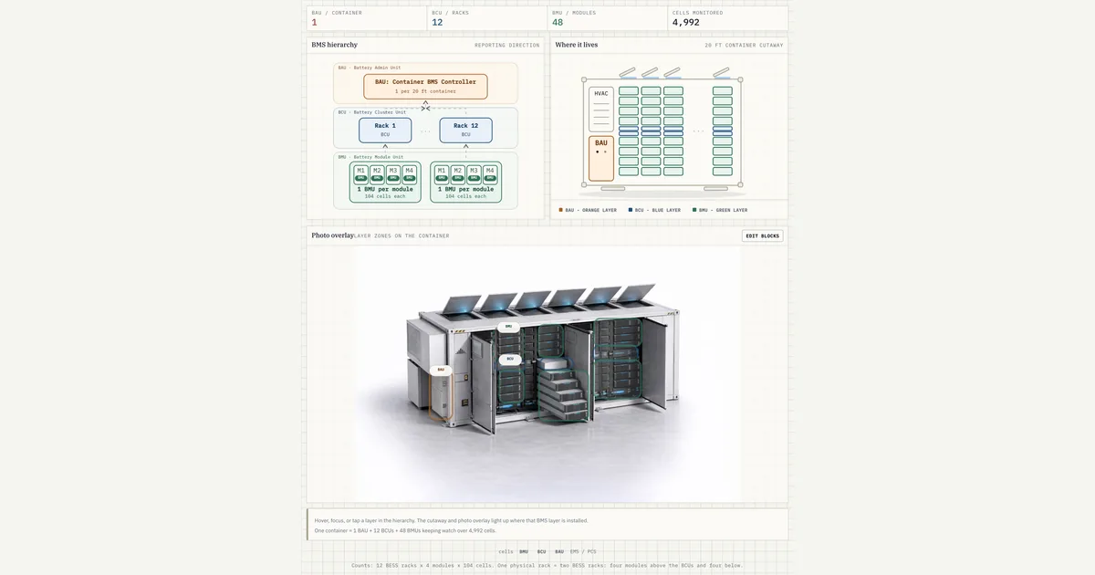 Interactive · bess.engineer ↗
 Key facts
| Position in hierarchy | Cell < module < rack < container < block/plant; smallest independently protected DC unit |
|---|---|
| Cell chemistry (default) | LFP, ~3.2 V nominal per cell (2.5–3.65 V window); NMC only as higher-density contrast |
| Series configuration (1,500 V class) | Typically ~360–416 cells in series — often four ~104S modules, more in earlier 48–52S designs |
| String voltage | ~1,150–1,330 V nominal, up to ~1,500 V max; 2,000 V class emerging |
| Rack energy (typical) | ~330–450 kWh DC nameplate for current 280–314 Ah LFP designs; older 1,000 V racks ~100–250 kWh |
| Racks per container | Commonly on the order of 8–16 paralleled per ~5 MWh, 20-ft container |
| Rack C-rate / current | 0.25C (4-h) to 0.5C (2-h); roughly ~70–200 A continuous depending on design |
| Protection / BMS layer | Main DC contactor or breaker, main fuse, pre-charge, sensing; rack BMS = BCU tier (BMU–BCU–BAU) |
| Equipment standards | UL 1973 (stationary battery, cell to rack), IEC 62619 (industrial Li cells and batteries), UL 9540 (full ESS) |
| Fire test method | UL 9540A thermal-runaway propagation test (a method producing data, not a rating) |
| Installation standard | NFPA 855; explosion control per NFPA 68 (venting) or NFPA 69 (prevention) |
| Role in lifecycle | Field-replaceable, independently isolatable unit; basis for augmentation increments and warranty remedies |
Typical values and standards
Rack energy has grown sharply with cell size. Older 1,000 V-class designs with 100–200 Ah cells landed around 100–250 kWh per rack; current 1,500 V-class racks built on 280–314 Ah LFP cells typically hold roughly 330–450 kWh (for example, 416 cells in series at 3.2 V and 314 Ah is about 418 kWh DC nameplate).
A modern 20-foot, ~5 MWh container commonly parallels on the order of 8–16 such racks. Rack current follows duration: a 4-hour system cycles its racks at 0.25C, a 2-hour system at 0.5C, so continuous rack current at nominal voltage typically falls in the ~70–200 A range depending on design.
Specifications you reconcile at the rack level include the string voltage window (minimum and maximum DC voltage versus the PCS operating range), maximum continuous and peak current, the main fuse and contactor interrupt ratings against the prospective DC short-circuit current of the paralleled bus, and the insulation-monitoring thresholds for the floating DC system. You also verify that paralleled racks share current acceptably and that state of charge imbalance between racks stays within the balancing budget of the BMS.
On standards: UL 1973 covers the battery from cell to pack and rack as stationary storage equipment, IEC 62619 is the international counterpart for industrial lithium cells and batteries, UL 9540 certifies the complete energy storage system, and UL 9540A is the thermal-runaway fire-propagation test method — a test method that produces data, not a pass/fail rating.
Its results feed NFPA 855 installation requirements; explosion control for the enclosure follows NFPA 68 (deflagration venting) or NFPA 69 (deflagration prevention). Default chemistry assumptions should be LFP, which dominates stationary BESS for thermal stability and cycle life; NMC racks offer higher energy density but higher thermal-runaway energy release, changing the spacing and venting analysis.
How it shows up in specs, studies and contracts
On a battery vendor datasheet, the rack (sometimes called a string or stack) gets its own table: cell configuration (for example 1P416S), nominal and min/max voltage, DC nameplate energy, continuous and peak current, weight, footprint, and the UL 1973 listing.
Check three things immediately: whether the quoted energy is BOL DC nameplate or usable within the warranted depth of discharge window, whether the voltage window actually sits inside the PCS DC operating range across the full temperature and state of charge span, and what the rack-level protection actually interrupts — some designs rely on fuses only, with the contactor rated for load switching, not fault clearing.
In studies, racks appear as parallel DC sources: DC short-circuit calculations sum the fault contribution of every paralleled rack to size fuses, busbars, and the PCS DC input; arc-flash and protection-coordination studies inherit those numbers. In commissioning and capacity tests, measured energy is usually reconciled per container but diagnosed per rack — one weak rack drags the whole parallel group, because the group's usable window is bounded by the first rack to hit a voltage limit.
In supply and warranty contracts, the rack is the natural unit for remedies: availability and capacity guarantees are measured at system level but cured by rack replacement, degradation tables assume a stated cycle count and depth of discharge profile per year, and augmentation options are priced per rack. Ask how mixing new racks with aged ones on a shared bus is handled — vendors typically require augmentation racks on a separate DC bus or dedicated PCS input, since paralleling fresh and faded racks forces the pack to the weakest string's window.
Common pitfalls
The most common trap is quoting rack energy without a reference point. A "418 kWh rack" is a BOL, DC-side, full-window nameplate; deliverable energy at the POI after depth of discharge limits, PCS and transformer losses, and years of fade is materially smaller, and contracted energy is different again. A related trap is treating rack count as fungible across vendors: two 5 MWh containers with 8 large racks versus 14 small ones have identical nameplates but different fault granularity, spare-parts strategy, and augmentation increments.
Watch vocabulary drift, too. Some vendors say "string" for the series assembly and "rack" for the physical frame, others use "stack" or "cluster"; in liquid-cooled pack-based architectures the classic serviceable rack blurs into larger welded assemblies that are not field-serviceable at module level. Always resolve what the smallest independently protected, independently replaceable DC unit actually is in the specific product — that, functionally, is the rack, whatever the brochure calls it.
Common misconception
A rack is basically just a bigger battery module — the terms are interchangeable.
In reality: A module is a sealed group of cells with local monitoring electronics; a rack is a series string of modules with its own rack BMS, main contactor, main fuse, and pre-charge circuit. The rack is the level at which a string is independently protected and isolated, which is why faults, capacity diagnostics, and augmentation are managed per rack, not per module.
Visuals & further reading
- Interactive: BESS Container Structure Interactive visual · bess.engineer
- Interactive: BMS Three-Layer Structure Interactive visual · bess.engineer
- BESS Fire Safety in 2026: Thermal Runaway, NFPA 855, and What the Incidents Taught Us Article
Rack, in context.
The Grid-Scale BESS course covers rack — and the rest of the system — from the ground up, the way it actually gets deployed.