Power Conversion System PCS
PCS & grid Essential term
Reviewed October 2026 by Sergey Syrvachev
The Power Conversion System (PCS) is a bidirectional inverter: it converts DC to AC when the battery discharges and rectifies AC to DC when it charges. Read it as a controllable, four-quadrant AC source: an operator sends real-power (P) and reactive-power (Q) setpoints and the converter holds them, bounded by three hard limits — a current ceiling in its semiconductors, the DC voltage window the battery can offer, and the AC voltage it can synthesize from that DC bus.
It is rated in apparent power (MVA or kVA), not MW alone, with utility-scale central blocks typically 1-5 MVA each, and it physically enforces the grid-code behaviour measured at the point of interconnection. Cells store energy; only the PCS delivers it.
Back to the free route: Electrical foundations — no cost, no account.
What it is (precise)
A PCS is a voltage-source converter, comprising power semiconductors, a DC link, filters, controls and protection, that moves power both ways between the DC battery bus and the AC bus. Four-quadrant operation means it independently sources or sinks real power (charge or discharge) and reactive power (absorb or supply VARs), so its operating point can sit anywhere inside its P-Q capability envelope. Internally it synthesizes the AC waveform by pulse-width modulation from the DC bus, switching IGBTs (increasingly silicon-carbide devices) at a few kHz and filtering to a near-sinusoidal output.
What the hardware limits is current. Semiconductors heat by the amperes through them, and reactive current heats them exactly as real current does, so the continuous rating is a current ceiling and the kVA on the nameplate is that ceiling read at a chosen voltage: S = √3 × V(L-L) × I, with S² = P² + Q². One utility-scale platform makes the point on its own datasheet: the largest frame is rated 3,674 A at 40 degrees C, and its published apparent power simply follows the AC voltage it is ordered for — 4,390 kVA at 690 V, 3,820 kVA at 600 V, 3,055 kVA at 480 V.
Three nameplates, one machine, one current. Two consequences matter. P and Q spend a single current budget, so reactive current ordered up during a voltage dip is bought with amperes that would otherwise have carried active power. And the transient ceiling sits close behind the continuous one, roughly 1.1-1.2 per unit of rated current against the 5-7 per unit a synchronous machine contributes, which is what makes fault levels and protection coordination on an inverter-based plant a different exercise.
In a grid-scale plant the PCS is one stage of a chain worth memorizing: battery racks feed a DC bus up to 1500 VDC in most current designs (2000 V is emerging); the PCS produces low-voltage AC, commonly 400-800 V (690 V class); and a step-up transformer raises that to medium voltage, typically 13.8-34.5 kV, for site collection.
The unit may be standalone or skid-integrated with its transformer and MV switchgear. Architectures split into central PCS (one large converter per battery block) and string or modular PCS (smaller converters near the racks); the choice trades efficiency, redundancy and cost.
Firmware, not hardware, decides the control mode. Grid-following injects current synchronized to a grid voltage that something else establishes; grid-forming actively sets voltage and frequency, behaving like a source behind an impedance. The silicon is largely shared, the control philosophy is not, and the two are distinct capabilities, never versions of one another. Either way the current ceiling is the same piece of physics; what changes is which quantity the controller defends when it runs into it.
Why it matters in a real grid-scale project
The PCS is where the project's commercial promises become physical. Nameplate AC power, the round-trip efficiency bid into the market, ramp rate, and ancillary services such as frequency response, voltage support and black start are all gated by the PCS, not the cells: a DC array only stores energy. Undersized conversion capacity turns directly into clipping / curtailment of deliverable power and lost revenue, which is why the AC-to-DC oversizing ratio is a headline design decision.
It is also the compliance enforcer. Interconnection agreements and grid codes impose ride-through, reactive-power and frequency- and voltage-response obligations. In North America these flow from IEEE 1547 (distribution), IEEE 2800 (transmission-connected inverter-based resources), ISO/RTO requirements and FERC rules (Order 842 primary frequency response; Orders 841 and 2222 storage market participation); internationally, the EU Network Codes or national grid codes apply.
Because they are met through PCS capability and settings, the PCS envelope drives plant sizing: how many units, how much oversizing against transformer and auxiliary losses, and how AC capacity maps to required DC energy.
Note where each number lives: capability is built at the converter's LV terminals, while the obligation is measured at the point of interconnection, and in between the step-up transformer absorbs reactive power rising with the square of the current it carries while the auxiliaries take real power off the top. The envelope at the terminals therefore has to be larger than the one written into the interconnection agreement.
Losses matter commercially and are easy to anchor. A PCS at roughly 97-99% one-way and a step-up transformer at roughly 99% each shave energy, and a full charge-discharge cycle passes through both twice, so round-trip efficiency lands near the square of the one-way figure and conversion alone can cost several percent before any battery loss. Efficiency is load-dependent: a converter that peaks near 98.5% between half and full load can fall off steeply below 10-20% load, exactly where a plant idles between dispatches, so tare and auxiliary draw surface in settlement data.
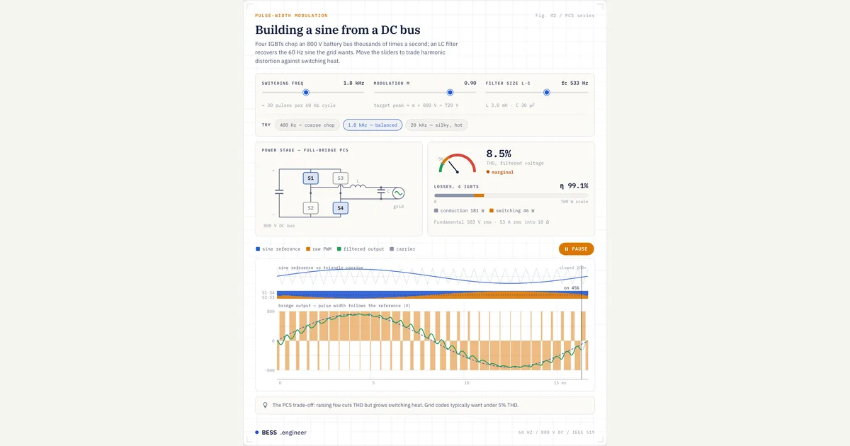 Interactive · bess.engineer ↗
 Key facts
| Function | Bidirectional 4-quadrant DC-AC; charges and discharges; independent P and Q control |
|---|---|
| Rating basis | Apparent power in MVA/kVA; S² = P² + Q² - read MVA first, never MW alone |
| Binding limit | Continuous AC current, not MW: S = √3 × V × I, so kVA tracks AC voltage on identical hardware |
| Same frame, three nameplates | 3,674 A at 40 degrees C = 4,390 kVA at 690 V, 3,820 at 600 V, 3,055 at 480 V (same frame) |
| P/Q trade | One current budget: Q ordered during a dip is bought with amperes that would have carried P |
| Typical unit rating | ~1-5 MVA per central PCS; string units low-hundreds of kVA; sites tens-hundreds of MW |
| kVA vs deliverable MW | 3.6 MVA at 0.95 PF ~ 3.4 MW; derate further at 45-50 C ambient / high altitude |
| Conversion efficiency | ~97-99% one-way peak; RTE ~ one-way squared; steep fall-off below ~10-20% load |
| DC bus voltage | Up to 1500 VDC typical (2000 V emerging); window must span battery full-charge to EOL |
| DC window floor | ~√2 × AC line voltage before full output: 976 V at 690 V AC, 849 V at 600 V AC |
| LV AC output | ~400-800 V (690 V class), stepped up via transformer to ~13.8-34.5 kV MV collection |
| Reactive capability | ~0.95 PF lead/lag at rated P; wider Q at part-load; STATCOM-like at P = 0 |
| Short-term overload | Often ~10% for minutes-scale periods; check the overload profile, not just continuous kVA |
| Product standard | UL 1741 SA/SB (grid support + ride-through per IEEE 1547); IEC 62477-1 in IEC markets |
| Grid-code standards | IEEE 1547 (distribution); IEEE 2800 (transmission-connected IBRs) |
| Safety vs fire test | UL 9540 = ESS safety cert; UL 9540A = fire-propagation TEST METHOD (feeds NFPA 855) |
Typical values and standards
Utility-scale central PCS blocks typically rate 1-5 MVA each and gang into plants of tens to hundreds of MW, while string-type units run in the low hundreds of kVA. Peak conversion efficiency is typically 97-99%, and weighted metrics such as CEC or Euro efficiency average performance across a standardized load profile for a more honest figure. Reactive capability is often specified to about 0.95 power factor leading or lagging at full output, with a wider Q range at reduced P. Output current distortion is normally held to a few percent THD, per IEEE 519-style harmonics limits.
Ratings are a matrix, not a single number, and this is the most misread part of a PCS datasheet. Nameplate kVA is quoted at a reference ambient (often 40-50 degrees C) and altitude (often 1000 m); beyond those it derates, and the same frame published at 4,390 kVA at 40 degrees C carries 4,075 kVA at 50 degrees C — about 7% surrendered to ambient alone. The DC window is the other axis.
Because the AC waveform is carved out of the DC bus, the converter needs a DC voltage above roughly √2 times its AC line-to-line voltage before it can synthesize full output, and that is exactly where the published windows start: 976 V for a 690 V machine, 849 V for a 600 V one, each running to 1500 V at the top. Set that against the battery.
A 1500 VDC string sits near 1,150-1,330 V nominal with a protected floor around 900-1,040 V cold and loaded, and ageing deepens the loaded sag, so the bottom of the converter's window and the bottom of the battery's fall in the same band and their overlap decides how much of the discharge is deliverable at full power at end of life.
Many units offer short-term overload (around 10% for minutes-scale periods) and can inject reactive power at zero real power, STATCOM-like while the battery rests. On standards, know which certificate covers what. The PCS is certified to UL 1741, with SA and SB supplements covering grid-support functions and abnormal-condition ride-through aligned with IEEE 1547 and verified per IEEE 1547.1; IEC-market projects reference IEC 62477-1 for converter safety.
At system level, UL 9540 is the safety certification for the complete ESS, of which the PCS is a listed component, while UL 9540A is a fire and thermal-runaway propagation test method whose data feeds NFPA 855, the installation standard. NFPA 68 (deflagration venting) and NFPA 69 (explosion prevention) apply at the battery enclosure, not the inverter.
How it shows up in specs, studies and contracts
On a datasheet, find the apparent-power rating first, then every condition bolted to it: reference temperature, altitude, AC voltage, cooling method.
Put six questions to the vendor: send the full derating curves; send the efficiency-versus-load curve, not just the peak; give the P-Q capability diagram at my site's ambient extremes; state the continuous and transient AC current limits and which current the controller gives up first when the voltage sags; confirm the DC voltage window against the battery's rack range at end of life; and state whether grid-forming ships in production firmware or is only roadmapped.
A DC-window mismatch strands usable energy without ever raising an alarm; a peak-only efficiency number hides the part-load penalty.
In interconnection studies the PCS appears as a dynamic model: utilities and ISOs increasingly require validated EMT and RMS models of the converter and its controls, and results for ride-through, weak-grid stability and harmonics are only as good as the match between model and shipping firmware.
In contracts, the PCS anchors the binding constraints: capacity tests at the point of interconnection, availability guarantees and efficiency warranties, while market rules hold the plant to frequency-response and ramp obligations only the PCS can execute. Whenever a spec or contract says MW, ask back: at what power factor, temperature and voltage.
Common pitfalls
The classic trap is reading a kVA rating as kW. A 3.6 MVA unit at 0.95 power factor delivers about 3.4 MW while still meeting its reactive obligation, and at 45-50 degrees C ambient it may deliver less; sizing a plant on nameplate kVA at 25 degrees C overstates deliverable power at the meter.
The circle also shrinks with voltage: hold the current ceiling while the grid sits at 0.9 per unit and the same converter passes about 10% less apparent power, which is exactly the condition in which the code asks it for more reactive support. A related error quotes output at the PCS terminals when the contract measures at the POI, after the transformer and the auxiliaries have taken their cut: that gap is the developer's problem, not the utility's, and it is where thin projects lose margin.
Two more trip-wires. First, treating AC-coupling and DC-coupling as interchangeable: in hybrid PV-plus-storage plants the PCS count, clipping recapture and loss chains differ fundamentally between the two.
Second, assuming any modern PCS simply does grid-forming: grid-forming operation changes fault current-limiting, protection coordination and model requirements, so if black start or islanded operation is in scope it must be specified, certified and tested, never inferred from a marketing slide. Confirm it in the firmware version you are actually buying, because the same chassis often ships both ways.
Sources & standards
Common misconception
The PCS is just an inverter, like a one-way solar inverter scaled up.
In reality: No. A BESS PCS is bidirectional and four-quadrant: it must charge as well as discharge and independently control reactive power, so it is rated and sold in MVA, not the MW a PV inverter implies. It absorbs and supplies VARs, can run STATCOM-like at zero real power, and, if the firmware is specified for it, can be grid-forming, actively setting voltage and frequency to enable services such as black start and islanding. A unidirectional PV inverter does none of these, which is why you cannot read a PV datasheet and a PCS datasheet the same way.
Visuals & further reading
- Interactive: PWM: Building a Sine from a DC Bus Interactive visual · bess.engineer
- Interactive: PCS Control Loop Interactive visual · bess.engineer
- Interactive: GFM Current Saturation Interactive visual · bess.engineer
- Interactive: PCS Dispatch Efficiency Interactive visual · bess.engineer
- Interactive: MV Skid Structure Interactive visual · bess.engineer
- P-Q capability Glossary
- POI capability envelope Glossary
- MVA headroom Glossary
- BESS Single-Line Diagram: How a Plant Is Wired Article
- BESS Commissioning and Capacity Testing Article
Power Conversion System, in context.
The Grid-Scale BESS course covers power conversion system — and the rest of the system — from the ground up, the way it actually gets deployed.